
Owner's manual


4-32
Ultra-High-Speed Flash
Microcontroller User’s Guide
PIS2-0
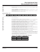
Bit 7, 6, 5
Priority Interrupt Status Bits 2-0. These bits indicate the level of interrupt that is currently being
serviced. (Interrupt levels 0-3 are associated with interrupt sources using the MP,LP bits found in
the IP1 and IP0 SFRS.)
Bit 4
SPTA1
Bit 3
SPRA1
Bit 2
SPTA0
Bit 1
SPRA0
Bit 0
This bit is reserved and reads a logic 1.
Serial Port 1 Transmit Activity Monitor. When set, this bit indicates that data is currently being
transmitted by serial port 1. It is cleared when the internal hardware sets the TI_1 bit. Do not alter
the clock divide control bits (PMR.7-6) while this bit is set or serial port data can be lost.
Serial Port 1 Receive Activity Monitor. When set, this bit indicates that data is currently being
received by serial port 1. It is clear
ed when the internal hardware sets the RI_1 bit. Do not alter the
clock divide control bits (PMR.7-6) while this bit is set or serial port data can be lost.
Serial Port 0 Transmit Activity Monitor. When set, this bit indicates that data is currently being
transmitted by serial por
t 0. It is cleared when the internal hardware sets the TI_1 bit. Do not alter
the clock divide control bits (PMR.7-6) while this bit is set or serial port data can be lost.
Serial Port 0 Receive Activity Monitor. When set, this bit indicates that data is currently being
received by serial por
t 0. It is cleared when the internal hardware sets the RI_1 bit. Do not alter the
clock divide control bits (PMR.7-6) while this bit is set or serial port data can be lost.
PIS2-0 INTERRUPT PRIORITY LEVEL
000 No interrupt in progress
001 Level 0 interrupt in progress
010 Level 1 interrupt in progress
011 Level 2 interrupt in progress
100 Level 3 interrupt in progress
101 Power-fail warning interrupt in progress
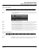
TA.7–0
Bits 7–0
Timed Access. Correctly accessing this register permits modification of timed access protected
bits. Write AAh to this register first, followed within 3 cycles by writing 55h. Timed access protected
bits can then be modified for a period of 3 cycles measured from the writing of the 55h.
W = Unrestricted write, -n = Value after reset
Timed Access Register (TA)
76543210
SFR C7h TA.7 TA.6 TA.5 TA.4 TA.3 TA.2 TA.1 TA.0
W-1 W-1 W-1 W-1 W-1 W-1 W-1 W-1
R = Unrestricted read, W = Unrestricted write, -n = Value after reset
Status Register (STATUS)
76543210
SFR C5 PIS2 PIS1 PIS0 — SPTA1 SPRA1 SPTA0 SPRA0
R-0 R-0 R-0 R-1 R-0 R-0 R-0 R-0
Maxim Integrated