
Owner's manual


4-22
Ultra-High-Speed Flash
Microcontroller User’s Guide
R = Unrestricted read, W = Unrestricted write, -n = Value after reset
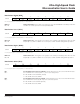
Serial Port 0 Control (SCON0)
SM0–2
Bits 7, 6, 5
Serial Port Mode. These bits control the mode of serial port 0. In addition the SM0 and SM2_0 bits
have secondary functions as shown.
SM0/FE_0
Bit 7
SM1_0
Bit 6
SM2_0
Bit 5
REN_0
Bit 4
TB8_0
Bit 3
RB8_0
Bit 2
TI_0
Bit 1
Framing Error Flag. When SMOD0 (PCON.6) = 0, this bit is used as a mode select bit (SM0) for
serial port 0. When SMOD0 (PCON.6) = 1, this bit becomes a framing error (FE) bit, which reports
detection of an invalid stop bit. When used as FE, this bit must be cleared in software. Once the
SMOD0 bit is set, modifications to this bit do not affect the serial port mode settings. Although
accessed from the same register, the data for bits SM0 and FE are stored internally in different
physical locations.
No Alternate Function.
Multiple CPU Communications. The function of this bit is dependent on the serial port 0 mode.
Mode 0: Selects period for synchronous serial port 0 data transfers.
Mode 1: When set, r
eception is ignored (RI_0 is not set) if invalid stop bit received.
Modes 2/3: When this bit is set, multiprocessor communications are enabled in modes 2 and 3.
This prevents the RI_0 bit from being set, and an interrupt being asserted, if the 9th bit received is not 1.
Receiver Enable. This bit enables/disables the serial port 0 receiver shift r
egister.
0 = Serial por
t 0 reception disabled.
1 = Serial port 0 receiver enabled (modes 1, 2, 3). Initiate synchronous reception (mode 0).
9th Transmission Bit State. This bit defines the state of the 9th transmission bit in serial port 0
modes 2 and 3.
9th Received Bit State. This bit identifies that state of the 9th reception bit of r
eceived data in ser-
ial por
t 0 modes 2 and 3. In serial port mode 1, when SM2_0 = 0, RB8_0 is the state of the stop
bit. RB8_0 is not used in mode 0.
Transmitter Interrupt Flag. This bit indicates that data in the serial port 0 buffer has been com-
pletely shifted out. In serial port mode 0, TI_0 is set at the end of the 8th data bit. In all other modes,
this bit is set at the end of the last data bit. This bit must be manually cleared by software.
7 6 5 4 3 2 1 0
SFR 98h S M0/FE_0 SM1_0 SM2_0 REN_0 TB8_0 RB8_0 TI_0 RI_0
RW-0 RW-0 RW-0 RW-0 RW-0 RW-0 RW-0 RW-0
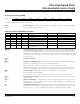
Table 4-10. Serial Port Mode Functions
SM0 SM1 SM2 MODE FU N C TION LENGTH ( BITS ) PERIOD
0 0 0 0 Synchronous 8 See P MR reg ister
0 0 1 0 Synchronous 8 See P MR reg ister
0 1 X 1 Asynchronous 10 Timer 1 or 2 baud rate equation
1 0 0 2 As ynchronous 11 See P MR reg ister
1 0 1 2
Asynchronous w ith mult i processor
communication
11 See PMR register
1 1 0 3 As ynchronous 11 Ti mer 1 or 2 baud rate equation
1 1 1 3
Asynchronous w ith mult i processor
communication
11 Timer 1 or 2 baud rate equation
Maxim Integrated