
Owner's manual


4-19
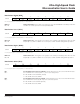
Table 4-9. MOVX Instruction
MD2, MD1, MD0 STRETCH VALUE MOVX DURATION
000 0 2 machine cycles
001 1
3 machine cycles
(default)
010 2 4 machine cycles
011 3 5 machine cycles
100 4 9 machine cycles
101 5 10 machine cycles
110 6 11 machine cycles
111 7 12 machine cycles
T2M
Bit 5
T1M
Bit 4
T0M
Bit 3
Timer 2 Clock Select. This bit controls the input clock that drives Timer 2. This bit has no effect
when the timer is in baud rate generator or clock output modes. See Timer Operation table.
Timer 1 Clock Select. This bit controls the input clock that drives Timer 1. See Timer Operation
table.
Timer 0 Clock Select. This bit contr
ols the input clock that drives Timer 0. See Timer Operation
table.
MD2, MD1, MD0
Bits 2, 1, 0
Stretch MOVX Select 2-0. These bits select the time by which external MOVX cycles are to be
stretched. This allows slower memory or peripherals to be accessed without using ports or manu-
al software intervention. The RD or WR strobe is stretched by the specified interval, which is trans-
parent to the software except for the increased time to execute to MOVX instruction. All internal
MOVX instructions are executed at the two machine cycle rate (0 stretch) independent of these bit
settings.
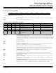
Table 4-8. Timer Operation (in Oscillator Clocks)
OSCILLAT OR CLO CKS
PER T IM ER (0, 1, 2) CLOCK
TxMH, TxM =
OSCILLAT OR CLO CKS PER
TIMER 2 CLOCK (BAUD R ATE G EN)
T2MH, T2M =
4X/2X CD1:0
00 01 1X XX
1 00 12 1 0.25 2
0 00 12 2 0.5 2
X 01 12 4 1 2
X 10 12 4 1 2
X 11 3072 1024 1024 2048
Ultra-High-Speed Flash
Microcontroller User’s Guide
Maxim Integrated