
Owner's manual


12-5
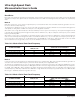
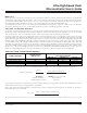
MODE 0
SERIAL PORT CLOCK FREQUENCY
SYSTEM CLOCK MODE
PMR REGISTER BITS
4X/2X, CD1, CD0
SM2 = 0 SM2 = 1
Crystal multiply mode 4X 100 OSC / 3 OSC / 1
Crystal multiply mode 2X 000 OSC / 6 OSC / 2
Divide-by-1 (default) X01, X10 OSC / 12 OSC / 4
Power-management mode (/1024) X11 OSC / 3072 OSC / 1024
Table 12-3. Mode 0 Serial Port Clock Frequency
Mode 2
In this asynchronous mode, baud rates are derived directly from the oscillator input. Table 12-4 summarizes baud-rate generation as
a function of the external oscillator frequency. This mode works identically to the original 8051 family.
The default case is divide-by-64. The user can effectively double the serial port clock frequency by setting the SMOD bit to a logic 1
for the associated UART. For serial port 0, the SMOD_0 bit is PCON.7. This is the original location in the 8051 family. For serial port 1,
the SMOD_1 bit is WDCON.7. When operating in the power management mode (CD1:0 = 11b), the serial port clock frequency is the
oscillator frequency divided by 16384 when the SMOD bit is a logic 0 and twice that frequency (OSC/8192) when the SMOD doubler
bit is a logic 1. SMOD bits default to a logic 0 on all resets.
MODE 2
SERIAL PORT C LOC K F REQU ENCY
SYSTEM CLOC K MO D E
PMR REGISTER BITS
4X/2X, CD1, CD0
SMOD = 0 SMOD = 1
C rys tal multi p ly mode 4X 100 OSC / 64 OSC / 32
C rys tal multi p ly mode 2X 000 OSC / 64 OSC / 32
D iv i de-by -1 ( default) X01, X10 OSC / 64 OSC / 32
Power- management mode (/1024) X11 OSC / 16384 O SC / 8192
Table 12-4. Mode 2 Serial Port Clock Frequency
Ultra-High-Speed Flash
Microcontroller User’s Guide
Baud Rates
Each mode has a baud-rate generator associated with it. This generator is generally the same for each UART. Several of the baud-rate
generation techniques have options that are independent for the two UARTs. The following baud-rate descriptions are separated by
mode.
Mode 0
Mode 0 is synchronous, so the shift clock output frequency is the baud rate. Table 12-3 summarizes baud-rate generation as a func-
tion of the external oscillator frequency.
The default case is divide-by-12. The user can select the shift clock frequency using the SM2 bit in the associated SCON register. For
serial port 0, the SM2_0 bit is SCON0.5. For serial port 1, the SM2_0 bit is SCON1.5.
When SM2 is set to a logic 0, the baud rate is fixed at a divide-by-12 of the system clock frequency, unless power-management mode
is invoked. When operating in power-management mode, with the SM2 bit clear ( = 0), the serial port clock frequency is the oscillator
frequency divided by 3072.
When SM2 is set to a logic 1, the baud rate is generated using the system clock frequency divided by 4, unless power-management
mode is invoked. When power-management mode is used with the SM2 bit set ( = 1), the serial port clock frequency tracks the sys-
tem clock frequency. Note that this use of SM2 differs from a standard 80C32. In that device, SM2 had no valid use when the UART
was in mode 0. Since it was generally set to a zero, for the divide-by-12, there is no compatibility problem.
Maxim Integrated