
Owner's manual


11-14
Ultra-High-Speed Flash
Microcontroller User’s Guide
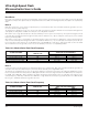
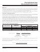
As discussed above, the watchdog timer has several SFR bits that contribute to its operation. It can be enabled to function as either
a reset source, interrupt source, software polled timer, or any combination of the three. Both the reset and the interrupt have status
flags. The watchdog also has a bit that restarts the timer. Table 11-5 shows the watchdog timer-related bits. Detailed bit descriptions
can be found in Section 4.
WATCHDOG TIMEOUT
(IN NUMBER OF OSCILLATOR CLOCKS)
SYSTEM CLOCK MODE
PMR REGISTER BITS
4X/2X, CD1, CD0
WD1:0 = 00b WD1:0 = 01b WD1:0 = 10b WD1:0 = 11b
Crystal multiply mode 4X 100 2
15
2
18
2
21
2
24
Crystal multiply mode 2X 000 2
16
2
19
2
22
2
25
Divide-by-1 (default) X01, X10 2
17
2
20
2
23
2
26
Power management mode
(divide-by-1024)
X11 2
27
2
30
2
33
2
36
Table 11-4. Watchdog Timeout Intervals
BIT N AMES D ESCRIPTIO N REGISTER LOCA TION BIT POSITIONS
EWT Enable watchdog timer reset WDCO N – D8h WD CON.1
RWT Reset watchdog timer WDCO N – D8h WDC ON.0
WD1,WD0 Watchdog interval control b its 1, 0 C KCON – 8Eh CKC ON.7,6
WTRF Watchdog ti mer reset flag WDCON – D8h WD CON.2
EWDI Enable watchdog timer interrupt EIE – E8h EIE.4
WDIF Watchdog inter rupt flag WDC ON – D8h WD CON.3
Table 11-5. Watchdog Timer-Related Bits
Maxim Integrated