
Owner's manual


10-6
Ultra-High-Speed Flash
Microcontroller User’s Guide
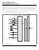
The special functions and the associated port pins are listed below:
P1.0 T2 Timer 2 output
P1.1 T2EX Timer 2 capture/reload input
P1.2 RXD1 Serial receive UART1
P1.3 TXD1 Serial transmit UART1
P1.4 INT2 External interrupt 2, rising-edge active
P1.5 INT3 External interrupt 3, falling-edge active
P1.6
INT4 External interrupt 4, rising-edge active
P1.7 INT5 External interrupt 5, falling-edge active
P3.0
RXD0 Serial receive UART0
P3.1 TXD0 Serial transmit UART0
P3.2 INT0 External interrupt 0, falling-edge active
P3.3 INT1 External interrupt 1, falling-edge active
P3.4
T0 Timer 0 input
P3.5 T1
Timer 1 input
P3.6 WR External data memory-write strobe
P3.7 RD External data memory-read strobe
Read-Modify-Write
The normal read instructions associated with the I/O ports read the pin state without regard to the port latches. However, the read-mod-
ify-write instructions read the state of the port latches instead of the port pins. This type of instruction reads the contents of an SFR,
then modifies it in the ALU, and returns it to the original source. The instructions of this type are listed below:
ANL Logical AND
ORL Logical OR
XRL Logical exclusive OR
JBC Branch if bit set and clear bit
CPL Complement bit
INC Increment
DEC Decrement
DJNZ Decrement and branch if not zero
MOV Px.n, C Move carry bit to bit n of port x
CLR Px.n Clear bit n in port x
SETB Px.n Set bit n in port x
Output Functions
The I/O ports appear to be true I/O, but their output characteristics are dependent on the individual port and pin conditions. When soft-
ware writes logic 0 to the port for output, the port is pulled to ground. When software writes logic 1 to the port for output, ports 1, 2, or
3 drive weak pullups (after the strong transition from 0 to 1). Thus, as long as the port is not heavily loaded, true logic values are out-
put. Port 0, having open-drain outputs, three-states when written to logic 1 and hence requires external pullups be present when used
as an output. DC drive capability is provided in the electrical specifications. Note that the DC current available from an I/O port pin is
a function of the permissible voltage drop.
Maxim Integrated