
Owner's manual


9-5
ally under control of the external signal, and the flag rises and falls with the pin level. All interrupt flags are evaluated on the final exe-
cution cycle of each instruction. A priority decoding process is performed among pending and new interrupt sources in order to select
the appropriate interrupt vector address. This decoding process is accomplished in a single memory cycle using combinatorial logic.
Hardware then forces an LCALL to the selected vector address in the following memory cycle, unless blocked by one of the following
conditions:
• An interrupt of equal or gr
eater priority has already been invoked and the RETI instruction has not been issued to terminate it.
• The current cycle is not the final cycle in the execution of the current instruction.
• The instruction in progress is an RETI or a write to IP0, IP1, EIP0, EIP1, IE, or EIE.
INTERRUPT
ENABLE BITS
INTERRUPT
VECTOR
INTERRUPT
SELECTION
HARDWARE
FLAG
BITS
PFI
INT0
TF0
TF1
RI 0
TI_0
RI_1
TI 1
TF2
EXF2
INT2
INT4
WATCHDOG
IT1
HIGHEST
PRIORITY
INDIVIDUAL
ENABLES
GLOBAL
ENABLE
INT1
INT3
INT5
INTERRUPT
PRIORITY BITS
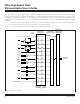
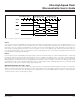
Figure 9-1. Interrupt Functional Description
Ultra-High-Speed Flash
Microcontroller User’s Guide
Maxim Integrated