
Owner's manual


9-2
Ultra-High-Speed Flash
Microcontroller User’s Guide
SECTION 9: INTERRUPTS
The ultra-high-speed microcontroller family improves upon the traditional 8051 architecture by utilizing a five-priority interrupt system.
The five priority levels, from highest priority to lowest, are 4, 3, 2, 1, and 0. The power-fail interrupt, when enabled, always receives the
highest priority (level 4), while other interrupt sources can be configured to level 3, 2, 1, or 0. Each source has independent priority
bits, flag(s), interrupt vector, and enable. In addition, interrupts can be globally enabled (or disabled). The interrupt system is com-
patible with the original 8051 family, having all of the original interrupts available. A summary of all interrupt sources is provided in the
table below.
Interrupt Overview
An interrupt allows the software to react to unscheduled or asynchronous events. When an interrupt occurs, the CPU is expected to
“service” the interrupt. This service takes the form of an interrupt service routine (ISR). The ISR resides at a predetermined address,
as shown in Table 9-1. When the interrupt occurs, the CPU vectors to this address and runs code created to service the interrupt. The
CPU stays in an interrupt service state until the return from interrupt instruction (RETI) is executed at completion of the ISR. When an
RETI is performed, the processor returns to the instruction that would have been next when the interrupt occurred. Once an ISR has
begun, it can be interrupted only by a higher priority interrupt.
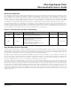
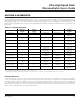
Table 9-1. Interrupt Summary
Unless marked, these flags must be cleared manually by software.
*Cleared automatically by hardware when the service routine is vectored to.
**If edge-triggered, cleared automatically by hardware when the service routine is vectored to. If level-triggered, flag follows the state of the pin.
INTERRU PT
INTERRU PT
V ECTOR
NATURAL
ORDER
FLAG ENABLE
PRIO RITY
CONTROL
Power-fa i l 33h 0 (h ighe s t) PFI (WDCON.4) EPFI (WD CON.5) N/ A
Externa l i n t errup t 0 03h 1 IE0 ( TCON.1)* * EX0 (IE.0)
MPX0 ( IP1.0)
LPX0 (IP0.0)
Ti m er 0 overf l ow 0 B h 2 TF 0 (TCON.5)* E T0 (IE.1)
MPT0 (IP1.1)
LPT0 (IP0.1)
Externa l i n t errup t 1 13h 3 IE1 (TCON.3)* * EX1 (IE.2)
MPX1 ( IP1.2)
LPX1 (IP0.2)
Ti m er 1 overf l ow 1 B h 4 TF 1 (TCON.7)* E T1 (IE.3)
MPT1 (IP1.3)
LPT1 (IP0.3)
Serial port 0 23 h 5
RI_0 (SCON0.0),
TI _ 0 (SCON0.1)
ES0 (IE.4)
MPS0 ( IP1.4)
LPS0 (IP0.4)
Ti m er 2 overf l ow 2 B h 6
TF2 (T2CON.7)
EXF2(T2CON.6)
ET2 (IE.5)
MPT2 (IP1.5)
LPT2 (IP0.5)
Serial port 1 3 B h 7
RI_1 (SCON1.0),
TI _ 1 (SCON1.1)
ES1 (IE.6)
MPS1 ( IP1.6)
LPS1 (IP0.6)
Externa l i n t errup t 2 43h 8 IE2 (EXIF.4) EX2 (EIE.0)
MPX2 (EIP1.0)
LPX2 (EIP0.0)
Externa l i n t errup t 3 4 B h 9 IE3 (EXIF.5) EX3 (EIE .1)
MPX3 (EIP1.1)
LPX3 (EIP0.1)
Externa l i n t errup t 4 53h 10 IE4 (EXIF.6) EX4 (EIE .2)
MPX4 (EIP1.2)
LPX4 (EIP0.2)
Externa l i n t errup t 5 5 B h 11 IE5 (EXIF.7) EX5 (EIE.3)
MPX5 (EIP1.3)
LPX5 (EIP0.3)
Watchdog int errup t 63 h 12 WDIF (WDCON.3) EWDI (E IE.4)
MPWDI (EIP1.4)
LPWDI (EIP0.4)
Maxim Integrated