
Owner's manual


7-9
Power Management Modes
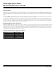
Power consumption in CMOS microcontrollers is a function of operating frequency. The power management mode (PMM) feature allows
software to dynamically match operating frequency and current consumption with the need for processing power. Instead of the default
one clock per machine cycle, PMM utilizes 1024 clocks per cycle to conserve power.
Several special features have been added to enhance the function of the PMM. The switchback feature allows the device to almost
instantaneously return to divide-by-1 mode upon detection of an enabled external interrupt or the receipt of a falling edge on a serial
port receiver pin. The advantages of this become apparent when one calculates the increased interrupt service time of a device oper-
ating in PMM. In addition, a device operating in PMM would normally be unable to sample an incoming serial transmission to proper-
ly receive it. The switchback feature, explained below, allows a device to return to divide-by-4 operation in time to receive incoming
serial port data and process interrupts with no loss in performance.
A status register (STATUS;C5h) prevents the device from accidentally reducing the clock rate during the servicing of an external inter-
rupt or serial port activity. This register can be interrogated to determine whether an interrupt is in progress, or if serial port activity is
occurring. Based on this information the software can delay or reject a planned change in the clock divider rate.
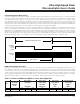
In addition, the ultra-high-speed flash microcontroller has the capability to operate from the internal ring oscillator during normal oper-
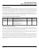
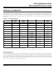
ation, not only during the crystal warmup period. Table 7-3 summarizes the new control bits associated with the power management
features.
Table 7-3. Power Management and Status Bit Summary
BIT N AME LO C A TION F U NC TION
RESET
STATE
REA D/ W RI TE AC CESS
C D1, CD0 P MR.7–6
C lock div i der control
C D1 C D0 osc cycles per s ystem clock cycle
0 0 C rys tal multi p l ier
0 1 Reserv ed
1 0 1 (reset default)
1 1 1024 (PMM)
10
Wr ite: 10 anyti me;
00, 01, and 11 only when
previously in 10 state.
Unrestricted read.
SWB PMR.5
Switchback enable
0 = Interrupts and serial port activity wil l not affect clock divi der
control bits
1 = Enabled interrupts and serial port activity wil l cause a
sw itchback
0 Unrestr icted
PIS2:PIS0 STATUS.7:5
Pr io r ity Interrupt Status
101 = Level 4 interrupt (power fai l ) in prog ress
100 = Level 3 interrupt in progress
011 = Level 2 interrupt in progress
010 = Level 1 interrupt in progress
001 = Level 0 interrupt in progress
000 = No interrupt in prog ress
0 Read only
SPTA1 STATUS.3
Serial port 1 transmitter activ ity status
0 = Serial port 1 trans mitter inactive
1 = Serial port 1 trans m itter active
0 Read only
SPRA1 STATUS.2
Serial port 1 receiver activ ity status
0 = Serial port 1 receiv er inactive
1 = Serial port 1 receiv er activ e
0 Read only
SPTA0 STATUS.1
Serial port 0 transmitter activ ity status
0 = Serial port 0 trans mitter inactive
1 = Serial port 0 trans m itter active
0 Read only
SPRA0 STATUS.0
Serial port 0 receiver activ ity status
0 = Serial port 0 receiv er inactive
1 = Serial port 0 receiv er activ e
0 Read only
Ultra-High-Speed Flash
Microcontroller User’s Guide
Maxim Integrated