
Owner manual


Secure Microcontroller User’s Guide
25 of 187
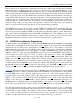
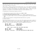
are selected during the bootstrap loading process and cannot be modified by the application software. The
table below shows the range values that can be selected when PM = 0 (partitionable).
RG1 RG0
RANGE
(kB)
CE1
ACCESS
CE2
ACCESS
1
1
64
0000–7FFFh
8000–FFFFh
1
0
32
0000–7FFFh
NA
0
1
16
0000–1FFFh
2000h–3FFFh
0
0
8
0000–1FFFh
NA
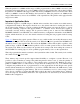
The total RAM space is partitionable, regardless of which range is selected. This contrasts with the
DS5000 that allowed partitioning of
CE1
only (see the following partition table). PA3–0 are the four
MSBs of the MCON register (MCON.7-4). Note that the partition values do not scale depending on
range. That is, if a range of less than 64kB is selected, the partition settings above the range should not be
unused. The microcontroller automatically decodes which RAM to enable, and uses the partition to
decide if this is program memory or data memory.
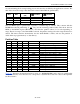
Partition Table
PA3 PA2 PA1 PA0 PARTITION BYTEWIDE BUS MEMORY MAP
0
0
0
0
0000h
0 Program, Data = Range
0
0
0
1
1000h
4kB Program, Data = Range – 4kB
0
0
1
0
2000h
8kB Program, Data = Range – 8kB
0
0
1
1
3000h
12kB Program, Data = Range – 12kB
0
1
0
0
4000h
16kB Program, Data = Range – 16kB
0
1
0
1
5000h
20kB Program, Data = Range – 20kB
0
1
1
0
6000h
24kB Program, Data = Range – 24kB
0
1
1
1
7000h
28kB Program, Data = Range – 28kB
1
0
0
0
8000h
32kB Program, Data = Range – 32kB
1
0
0
1
9000h
36kB Program, 28kB Data
1
0
1
0
A000h
40kB Program, 24kB Data
1
0
1
1
B000h
44kB Program, 20kB Data
1
1
0
0
C000h
48kB Program, 16kB Data
1
1
0
1
D000h
52kB Program, 12kB Data
1
1
1
0
E000h
56kB Program, 8kB Data
1
1
1
1
FFFFh
64kB Program, 0kB Data
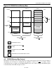
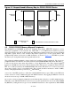
Figure 4-4 illustrates the functional memory map of a DS5001/DS5002 series device in partitionable
mode. Note that any access that does not correspond to a bytewide bus location is routed to the expanded
bus Ports 0 and 2.