
Datasheet


MAX9984
SiGe High-Linearity, 400MHz to 1000MHz
Downconversion Mixer with LO Buffer/Switch
_______________________________________________________________________________________ 3
Note 1: All limits include external component losses. Output measurements taken at IF output of the Typical Application Circuit.
Note 2: Operation outside this range is possible, but with degraded performance of some parameters.
Note 3: See Table 2 for component list required for 400MHz to 500MHz operation. For operation from 500MHz to 800MHz, appropriate
tuning is required; please contact the factory for support.
Note 4: Compression point characterized. It is advisable not to operate continuously the mixer RF input above +12dBm.
Note 5: Guaranteed by design and characterization.
Note 6: Measured with external LO source noise filtered so the noise floor is -174dBm/Hz. This specification reflects the effects of all
SNR degradations in the mixer, including the LO noise as defined in Maxim Application Note 2021.
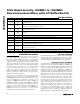
AC ELECTRICAL CHARACTERISTICS (continued)
(MAX9984 Typical Application Circuit, using component values in Table 1, V
CC
= +4.75V to +5.25V, RF and LO ports are driven from
50Ω sources, P
LO
= -3dBm to +3dBm, P
RF
= -5dBm, f
RF
= 815MHz to 1000MHz, f
LO
= 570MHz to 850MHz, f
IF
= 160MHz, f
RF
> f
LO
,
T
C
= -40°C to +85°C, unless otherwise noted. Typical values are at V
CC
= +5V, P
RF
= -5dBm, P
LO
= 0dBm, f
RF
= 910MHz, f
LO
=
750MHz, f
IF
= 160MHz, T
C
= +25°C, unless otherwise noted.) (Note 1)
PARAMETER SYMBOL CONDITIONS MIN TYP MAX UNITS
T
C
= +25°C to -40°C -1.5
Input IP3 Variation Over
Temperature
T
C
= +25°C to +85°C +0.8
dB
Noise Figure NF Single sideband, f
IF
= 190MHz 9.3 dB
P
B LOC K E R
=
+ 8d Bm
19
Noise Figure Under-Blocking
f
R F
= 900M H z ( no si g nal )
f
L O
= 1090M H z
f
B LOC K E R
= 981M H z
f
I F
= 190M H z
( N ote 6)
P
B LOC K E R
=
+ 11d Bm
24
dB
P
B LOC K E R
=
+ 8d Bm
0.25
Small-Signal Compression
Under-Blocking Condition
P
FUNDAMENTAL
= -5dBm
f
F U N D A M E N TA L
= 910M H z
f
B LOC K E R
= 911M H z
P
B LOC K E R
=
+ 11d Bm
0.6
dB
LO Drive -3 +3 dBm
P
RF
= -10dBm 71
2 x 2 2RF-2LO
P
RF
= -5dBm 66
P
RF
= -10dBm 87
Spurious Response at IF
3 x 3 3RF-3LO
P
RF
= -5dBm 82
dBc
LO2 selected 47 54
LO1 to LO2 Isolation
P
LO
= +3dBm
T
C
= +25°C (Note 5)
LO1 selected 47 60
dB
LO Leakage at RF Port P
LO
= +3dBm -32 dBm
LO Leakage at IF Port P
LO
= +3dBm -23 dBm
RF-to-IF Isolation P
LO
= +3dBm 54 dB
LO Switching Time 50% of LOSEL to IF settled to within 2° 50 ns
RF Port Return Loss 14 dB
LO1/2 port selected,
LO2/1 and IF terminated
23
LO Port Return Loss
LO1/2 port unselected,
LO2/1 and IF terminated
20
dB
IF Port Return Loss
LO driven at 0dBm, RF terminated into 50Ω,
differential 200Ω
16 dB