
Datasheet


MAX9744
20W Stereo Class D Speaker Amplifier
with Volume Control
16 ______________________________________________________________________________________
Volume Control
For maximum flexibility, the MAX9744 features volume
control operation using an analog voltage input or
through the I
2
C interface. To set the device to analog
mode, connect ADDR1 and ADDR2 to GND. In analog
mode, SDA/VOL is an analog input for volume control.
The analog input range is ratiometric between 0.9 x
V
DD
and 0.1 x V
DD
where 0.9 x V
DD
= full mute and 0.1
x V
DD
= full volume (Table 7).
Use ADDR1 and ADDR2 to select I
2
C mode. There are
three addresses that can be chosen, allowing for multi-
ple devices on a single bus (Table 4). In I
2
C mode, vol-
ume is controlled by choosing the speaker volume
control register in the command byte (Table 5). There
are 64 volume settings, where the lowest setting is full
mute (Table 6). See the
Write Byte
section for more
information on formatting data and tables to set volume
levels. The default volume after power-up is position 40
(-7.1dB) (see Table 7).
I
2
C Interface
The MAX9744 features an I
2
C 2-wire serial interface
consisting of a serial-data line (SDA) and a serial-clock
line (SCL). SDA and SCL facilitate communication
between the MAX9744 and the master at clock rates up
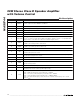
to 400kHz. Figure 3 shows the 2-wire interface timing
diagram. The MAX9744 is a receive-only slave device,
relying on the master to generate the SCL signal. The
MAX9744 cannot write to the SDA bus except to
acknowledge the receipt of data from the master. The
master, typically a microcontroller, generates SCL and
initiates data transfer on the bus.
A master device communicates to the MAX9744 by
transmitting the proper address followed by the data
word. Each transmit sequence is framed by a START (S)
or Repeated START (Sr) condition and a STOP (P) condi-
tion. Each word transmitted over the bus is 8 bits long
and is always followed by an acknowledge clock pulse.
The MAX9744 SDA line operates as both an input and
an open-drain output. A pullup resistor, greater than
500Ω, is required on the SDA bus. The MAX9744 SCL
line operates as an input only. A pullup resistor, greater
than 500Ω, is required on SCL if there are multiple mas-
ters on the bus, or if the master in a single-master sys-
tem has an open-drain SCL output. Series resistors in
line with SDA and SCL are optional. The SCL and SDA
inputs have Schmitt trigger and filter circuits that sup-
press noise spikes to assure proper device operation
even on a noisy bus.
SCL
SDA
START
CONDITION
STOP
CONDITION
REPEATED
START
CONDITION
START
CONDITION
t
HD, STA
t
SU, STA
t
HD, STA
t
SP
t
BUF
t
SU, STO
t
LOW
t
SU, DAT
t
HD, DAT
t
HIGH
t
R
t
F
Figure 3. 2-Wire Serial-Interface Timing Diagram