
Datasheet


MAX9744
20W Stereo Class D Speaker Amplifier
with Volume Control
______________________________________________________________________________________ 13
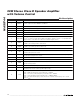
Pin Description (continued)
PIN NAME FUNCTION
26 SYNCOUT SYNC Signal Output
31, 32 OUTR+ Right-Channel Positive Speaker Output
33 BOOTR+
Right-Channel Positive Speaker Output Boost Flying-Capacitor Connection. Connect a 0.1µF
ceramic capacitor between BOOTR+ and OUTR+.
34, 35, 39,
43, 44
PGND Power Ground
36, 37 OUTR- Right-Channel Negative Speaker Output
38 BOOTR-
Right-Channel Negative Speaker Output Boost Flying-Capacitor Connection. Connect a 0.1µF
ceramic capacitor between BOOTR- and OUTR-.
40 BOOTL-
Left-Channel Negative Speaker Output Boost Flying-Capacitor Connection. Connect a 0.1µF
ceramic capacitor between BOOTL- and OUTL-.
41, 42 OUTL- Left-Channel Negative Speaker Output
—EP
Exposed Pad. The external pad lowers the package’s thermal impedance by providing a direct
heat conduction path from the die to the PCB. Connect the exposed thermal pad to PGND.
Detailed Description
The MAX9744 20W filterless, stereo Class D audio
power amplifier offers Class AB performance with Class
D efficiency with a minimal board space solution. The
MAX9744 features a spread-spectrum modulation
scheme offering significant improvements to switch-
mode amplifier technology. This device features analog
or digitally adjustable volume control, externally set
input gain, shutdown mode, SYNC input and output,
mute, and industry-leading click-and-pop suppression.
The MAX9744 features extensive click-and-pop sup-
pression circuitry that eliminates audible clicks-and-
pops at startup and shutdown.
The MAX9744 features a 64-step, dual-mode (analog
or I
2
C) volume control and mute function. In analog vol-
ume control mode, the voltage applied to SDA/VOL
sets the volume level. Two address inputs (ADDR1,
ADDR2) set the volume control function between ana-
log and I
2
C mode and set the slave address. In I
2
C
mode, there are three selectable slave addresses
allowing for multiple devices on a single bus.
The MAX9744 offers spread-spectrum and fixed-fre-
quency modes of operation with classic PWM or filter-
less modulation output schemes. The filterless
modulation scheme uses minimum pulse outputs when
the audio inputs are at the zero crossing. As the input
voltage increases or decreases, the duration of the
pulse at one output increases while the other output
pulse duration remains the same. This causes the net
voltage across the speaker (V
OUT+
- V
OUT-
) to change.
The minimum-width pulse topology reduces EMI and
increases efficiency.
Operating Modes
Fixed-Frequency Modulation Mode
The MAX9744 features two fixed-frequency modes:
300kHz and 360kHz. Connect SYNC to GND to select
300kHz switching frequency; leave SYNC unconnected
to select the 360kHz switching frequency. The
MAX9744 frequency spectrum consists of the fundamen-
tal switching frequency and its associated harmonics
(see the Wideband Output Spectrum graphs in the
Typical
Operating Characteristics
). For applications where exact
spectrum placement of the switching fundamental is
important, program the switching frequency so that the
harmonics do not fall within a sensitive frequency band
(Table 1). Audio reproduction is not affected by chang-
ing the switching frequency.