
Datasheet

MAX9736
Mono/Stereo High-Power Class D Amplifier
______________________________________________________________________________________ 13
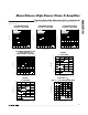
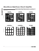
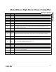
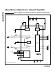
Pin Description
PIN NAME FUNCTION
1, 2 OUTL- Left-Channel Negative Speaker Output
3 BOOT Charge-Pump Output. Connect a 1μF charge-pump holding capacitor from BOOT to PVDD.
4 MONO Mono Select. Set MONO high for mono mode, low for stereo mode.
5 FBL Left-Channel Feedback. Connect feedback resistor between FBL and INL to set amplifier gain.
6 INL Stereo Left-Channel Inverting Input. In mono mode, INL is the inverting audio input for the mono amplifier.
7, 8, 17 N.C. No Connection. Not internally connected. OK to connect to PGND.
9 MUTE Mute Input. Drive MUTE low to place the device in mute mode.
10 SHDN Shutdown Input. Drive SHDN low to place the device in shutdown mode.
11 REGEN
Internal Regulator Enable Input. Connect REGEN to SHDN
to enable the internal regulator. Drive REGEN
low to disable the internal regulator, and supply the device with an external 5V supply on VS. See the
Power-Supply Sequencing section.
12 COM Internal 2V Bias. Bypass COM to AGND with a 1μF capacitor.
13, 14 AGND Analog Ground
15 REG Internal Regulator Output. Bypass REG to AGND with a 1μF capacitor.
16 VS
5V Regulator Supply. Bypass VS to AGND with a 1μF capacitor. If REGEN is low, the internal regulator is
disabled, and an external 5V supply must be connected to VS. See the Power-Supply Sequencing
section.
18 INR
Stereo Right-Channel Inverting Audio Input. In mono mode, INR is the inverting audio input for the
uncommitted preamplifier (see the Mono Configuration section for more details).
19 FBR Right-Channel Feedback. Connect feedback resistor between FBR and INR to set amplifier gain.
20 MOD
Output Modulation Select. Sets the output modulation scheme:
V
MOD
= Low, classic PWM/fixed-frequency mode
V
MOD
= High, filterless modulation/spread-spectrum mode
21 C1N Charge-Pump Flying-Capacitor Negative Terminal
22 C1P Charge-Pump Flying-Capacitor Positive Terminal
23, 24 OUTR- Right-Channel Negative Speaker Output
25, 26 OUTR+ Right-Channel Positive Speaker Output
27, 30 PVDD
Power Supply. Bypass each PVDD pin to ground with 0.1μF capacitors. Also, use a single 220μF
capacitor between PVDD and PGND.
28, 29 PGND Power Ground
31, 32 OUTL+ Left-Channel Positive Speaker Output
— EP Exposed Pad. Must be externally connected to PGND.