
Datasheet


5Maxim Integrated
Gigabit Multimedia Serial Link with Spread
Spectrum and Full-Duplex Control Channel
MAX9259/MAX9260
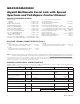
MAX9259 AC ELECTRICAL CHARACTERISTICS
(V
DVDD
= V
AVDD
= 1.7V to 1.9V, V
IOVDD
= 1.7V to 3.6V, R
L
= 100I Q1% (differential), T
A
= -40NC to +105NC, unless otherwise noted.
Typical values are at V
DVDD
= V
AVDD
= V
IOVDD
= 1.8V, T
A
= +25NC.)
PARAMETER
SYMBOL CONDITIONS MIN TYP MAX UNITS
PARALLEL CLOCK INPUT (PCLKIN)
Clock Frequency
f
PCLKIN
V
BWS
= V
GND
, V
DRS
= V
IOVDD
8.33 16.66
MHz
V
BWS
= V
GND
, V
DRS
= V
GND
16.66 104
V
BWS
= V
IOVDD
, V
DRS
= V
IOVDD
6.25 12.5
V
BWS
= V
IOVDD
, V
DRS
= V
GND
12.5 78
Clock Duty Cycle
DC t
HIGH
/t
T
or t
LOW
/t
T
(Figure 5) 35 50 65 %
Clock Transition Time
t
R
, t
F
(Figure 5) 4 ns
Clock Jitter
t
J
3.125Gbps, 300kHz sinusoidal jitter 800 ps
(P-P)
I
2
C/UART PORT TIMING (Note 3)
Output Rise Time
t
R
30% to 70%, C
L
= 10pF to 100pF, 1kI
pullup to IOVDD
20 150 ns
Output Fall Time
t
F
70% to 30%, C
L
= 10pF to 100pF, 1kI
pullup to IOVDD
20 150 ns
Input Setup Time
t
SET
I
2
C only (Figure 6) 100 ns
Input Hold Time
t
HOLD
I
2
C only (Figure 6) 0 ns
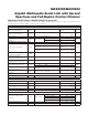
SWITCHING CHARACTERISTICS (Note 3)
Differential Output Rise-and-Fall
Time
t
R
, t
F
20% to 80%, V
OD
≥ 400mV, R
L
= 100I,
serial-data rate = 3.125Gbps
90 150 ps
Total Serial Output Jitter
t
TSOJ1
3.125Gbps PRBS signal, measured at
V
OD
= 0V differential, preemphasis
disabled (Figure 7)
0.25 UI
Deterministic Serial Output Jitter
t
DSOJ2
3.125Gbps PRBS signal 0.15 UI
Parallel Data Input Setup Time
t
SET
(Figure 8) 1 ns
Parallel Data Input Hold Time
t
HOLD
(Figure 8) 1.5 ns
Serializer Delay (Note 4)
t
SD
(Figure 9)
Spread spectrum enabled 2830
Bits
Spread spectrum disabled 270
Link Start Time
t
LOCK
(Figure 10) 3.5 ms
Power-Up Time
t
PU
(Figure 11) 3.5 ms
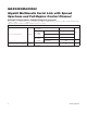
I
2
S INPUT TIMING
WS Frequency
f
WS
(Table 2) 8 192 kHz
Sample Word Length
n
WS
(Table 2) 4 32 Bits
SCK Frequency
f
SCK
f
SCK
= f
WS
x n
WS
x 2
(8 x 4)
x 2
(192 x
32) x 2
kHz
SCK Clock High Time (Note 3)
t
HC
V
SCK
≥ V
IH
, t
SCK
= 1/f
SCK
0.35 x
t
SCK
ns
SCK Clock Low Time (Note 3)
t
LC
V
SCK
≤ V
IL
, t
SCK
= 1/f
SCK
0.35 x
t
SCK
ns
SD, WS Setup Time
t
SET
(Figure 12, Note 3) 2 ns
SD, WS Hold Time
t
HOLD
(Figure 12, Note 3) 2 ns