
Datasheet


MAX9121/MAX9122
Quad LVDS Line Receivers with
Integrated Termination and Flow-Through Pinout
8 _______________________________________________________________________________________
Cables and Connectors
Transmission media typically have a controlled differen-
tial impedance of 100Ω. Use cables and connectors
that have matched differential impedance to minimize
impedance discontinuities.
Avoid the use of unbalanced cables such as ribbon or
simple coaxial cable. Balanced cables such as twisted
pair offer superior signal quality and tend to generate
less EMI due to magnetic field canceling effects.
Balanced cables pick up noise as common mode,
which is rejected by the LVDS receiver.
Termination
The MAX9122 has an integrated termination resistor
connected across the inputs of each receiver. The
value of the integrated resistor is specified in the DC
characteristics.
The MAX9121 requires an external termination resistor.
The termination resistor should match the differential
impedance of the transmission line. Termination resis-
tance values may range between 90Ω to 132Ω,
depending on the characteristic impedance of the
transmission medium.
When using the MAX9121, minimize the distance
between the input termination resistors and the
MAX9121 receiver inputs. Use 1% surface-mount resis-
tors.
IN_+
IN_-
OUT_
RECEIVER ENABLED
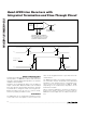
1/4 MAX9121/MAX9122
50Ω REQUIRED FOR PULSE GENERATOR.
WHEN TESTING THE MAX9122, ADJUST THE
PULSE GENERATOR OUTPUT TO ACCOUNT
FOR INTERNAL TERMINATION RESISTOR.
*
**
PULSE
GENERATOR**
50Ω*50Ω*
C
L
Figure 2. Propagation Delay and Transition Time Test Circuit
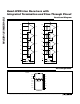
Figure 3. Propagation Delay and Transition Time Waveforms
IN_-
IN_+
OUT_
50%
V
ID
V
OL
V
OH
V
ID
= 0
20%20%
80% 80%
t
PHLD
t
PLHD
t
THL
t
TLH
V
ID
= 0
50%
V
ID
= (V
IN_+
) - (V
IN_-
)
NOTE: V
CM
= (V
IN-
+ V
IN+
)
2