
Datasheet


MAX690T/S/R, 704T/S/R, 802T/S/R, 804–806T/S/R
3.0V/3.3V Microprocessor Supervisory Circuits
4 _______________________________________________________________________________________
nA
-500 2 500
PFI Input Current
-25 2 25
MIN TYP MAX
ns100 20t
MR
–
M
—
R
–
Pulse Width
V
0.3 x V
CC
V
IH
–
M
—
R
–
Input Threshold
0.7 x V
CC
ns60 500t
MD
–
M
—
R
–
to Reset Delay
µA20 60 350
–
M
—
R
–
Pull-Up Current
V
0.7 x V
CC
V
IH
0.3 x V
CC
V
IL
WDI Input Threshold
1.12 1.60 2.24
ns100 20WDI Pulse Width
V
IL
MAX690_M, MAX802_M,
MAX804_M, MAX805_M
-1 +0.01 +1
-10 +0.01 +10
µAWDI Input Current
MAX690/MAX802/MAX804/
MAX805 only
st
WD
Watchdog Timeout Period
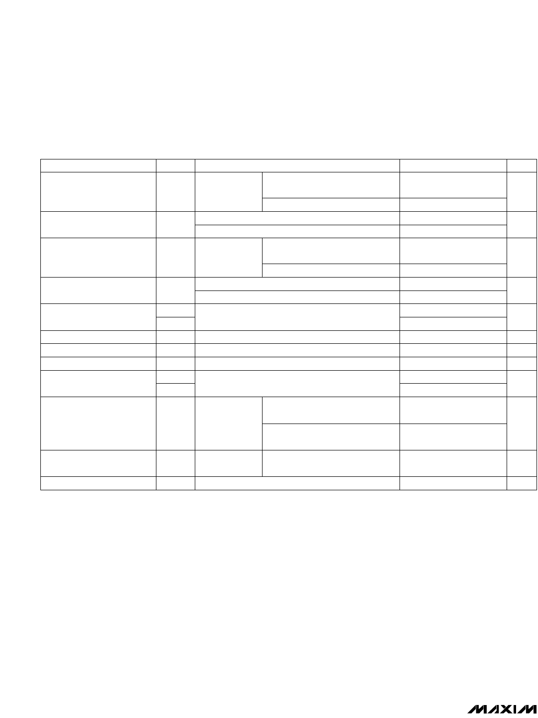
Note 1: V
CC
supply current, logic input leakage, watchdog functionality (MAX690_/802_/805_/804_),
–
M
—
R
–
functionality
(MAX704_/806_), PFI functionality, state of
–
R
—
E
—
S
—
E
—
T
–
(MAX690_/704_/802_/806_), and RESET (MAX804_/805_) tested at
VBATT = 3.6V, and V
CC
= 5.5V. The state of
–
R
—
E
—
S
—
E
—
T
–
or RESET and
–
P
—
F
—
O
–
is tested at V
CC
= V
CC
min.
Note 2: Tested at VBATT = 3.6V, V
CC
= 3.5V and 0V. The battery current will rise to 10µA over a narrow transition window around
V
CC
= 1.9V.
Note 3: Leakage current into the battery is tested under the worst-case conditions at V
CC
= 5.5V, VBATT = 1.8V and at V
CC
= 1.5V,
VBATT= 1.0V.
Note 4: Guaranteed by design.
Note 5: When V
SW
> V
CC
> VBATT, V
OUT
remains connected to V
CC
until V
CC
drops below VBATT. The V
CC
-to-VBATT comparator
has a small 25mV typical hysteresis to prevent oscillation. For V
CC
< 1.75V (typ), V
OUT
switches to VBATT regardless of the
voltage on VBATT.
Note 6: When VBATT > V
CC
> V
SW
, V
OUT
remains connected to V
CC
until V
CC
drops below the battery switch threshold (V
SW
).
Note 7: V
OUT
switches from VBATT to V
CC
when V
CC
rises above the reset threshold, independent of VBATT. Switchover back to
V
CC
occurs at the exact voltage that causes
–
R
—
E
—
S
—
E
—
T
–
to go high (on the MAX804_/805_, RESET goes low); however
switchover occurs 200ms prior to reset.
Note 8: The reset threshold tolerance is wider for V
CC
rising than for V
CC
falling to accommodate the 10mV typical hysteresis, which
prevents internal oscillation.
Note 9: The leakage current into or out of the RESET pin is tested with RESET asserted (RESET output high impedance).
MAX690_/MAX704_/MAX805_
V
1.187 1.237 1.287
V
PFT
PFI Input Threshold
1.212 1.237 1.262
SYMBOLPARAMETER UNITS
MAX704_/MAX806_ only
MAX704_/MAX806_ only
MAX704_/MAX806_ only,
–
M
—
R
–
= 0V, V
CC
= 3V
0V< V
CC
< 5.5V
MAX704_/MAX806_ only
MAX690_M, MAX704_M, MAX80_ _M
V
CC
< 3.6V
V
PFI
falling
CONDITIONS
MAX690_/MAX802_/MAX804_/MAX805_ only
V
CC
< 3.6V
MAX690_C/E, MAX704_C/E, MAX80_ _C/E
MAX802_C/E, MAX804_C/E,
MAX806_C/E
MAX690_C/E, MAX802_C/E,
MAX804_C/E, MAX805_C/E
MAX690_/MAX802_/MAX804_/MAX805_ only
MAX690_M, MAX704_M, MAX80_ _M
mV
10 25
nA
-500 2 500
PFI Input Current
-25 2 25
V
PFH
PFI Hysteresis, PFI Rising
10 20
MAX690_M, MAX704_M, MAX80_ _M
V
CC
< 3.6V
MAX690_C/E, MAX704_C/E, MAX80_ _C/E
MAX690_C/E, MAX704_C/E,
MAX80_ _C/E
ELECTRICAL CHARACTERISTICS (continued)
(V
CC
= 3.17V to 5.5V for the MAX690T/MAX704T/MAX80_T, V
CC
= 3.02V to 5.5V for the MAX690S/MAX704S/MAX80_S, V
CC
= 2.72V to
5.5V for the MAX690R/MAX704R/MAX80_R; VBATT = 3.6V; T
A
= T
MIN
to T
MAX
; unless otherwise noted. Typical values are at T
A
= +25˚C.)