
Datasheet


The snapshot is continuously compared with the actual
input conditions, and if a change is detected for any port
input, then an internal transition flag is set for that port,
and INT is asserted to signal a state change. The four
port inputs are sampled (internally latched into the
snapshot register) and the old transition flags cleared
during the I
2
C acknowledge of every MAX7322 read
and write access. The previous port transition flags are
read through the serial interface as the second byte of
a 2-byte read sequence.
A long read sequence (more than 2 bytes) can be used
to poll the expander continuously without the overhead
of resending the slave address. If more than 2 bytes
are read from the expander, the expander repeatedly
returns the input port data alternating with the transition
flags. The inputs are repeatedly resampled and the
transition flags repeatedly reset for each pair of bytes
read. All changes that occur during a long read
sequence are detected and reported.
The MAX7322 includes a 4-bit interrupt mask register
that selects which inputs generate an interrupt upon
change. Each input’s transition flag is set when its input
changes, independent of the interrupt mask register
settings. The interrupt mask register allows the
processor to be interrupted for critical events, while the
inputs and the transition flags can be polled periodically
to detect less-critical events.
The INT output is not reasserted during a read sequence
to avoid recursive reentry into an interrupt service
routine. Instead, if a data change occurs that would
normally cause the INT output to be set, the INT assertion
is delayed until the STOP condition. INT is not reassert-
ed upon a STOP condition if the changed input data is
read before the STOP occurs. The INT logic ensures
that unnecessary interrupts are not asserted, yet data
changes are detected and reported no matter when the
change occurs.
Transition Detection Masks
The transition detection logic incorporates a change
flag and an interrupt mask bit for each of the four input
ports. The four change flags can be read through the
serial interface, and the 4-bit interrupt mask is set
through the serial interface.
Each port’s change flag is set when that port’s input
changes, and the change flag remains set even
if the input returns to its original state. The port’s
interrupt mask determines whether a change on that input
port generates an interrupt. Enable interrupts for high-
priority inputs using the interrupt mask. The interrupt allows
the system to respond quickly to changes on these
inputs. Poll the MAX7322 periodically to monitor less-
important inputs. The change flags indicate whether a
permanent or transient change has occurred on any input
since the MAX7322 was last accessed.
Port Outputs
Write one byte to the MAX7322 to set the output port
levels for the four push-pull outputs, and the interrupt
mask for the four inputs simultaneously.
Serial Interface
Serial Addressing
The MAX7322 operates as a slave that sends and
receives data through an I
2
C interface. The interface uses
a serial-data line (SDA) and a serial-clock line (SCL) to
achieve bidirectional communication between master(s)
and slave(s). The master initiates all data transfers to
and from the MAX7322 and generates the SCL clock that
synchronizes the data transfer (Figure 1).
SDA operates as both an input and an open-drain output.
A pullup resistor, typically 4.7kΩ, is required on SDA.
SCL operates only as an input. A pullup resistor, typically
4.7kΩ, is required on SCL if there are multiple masters
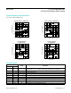
Figure 1. 2-Wire Serial Interface Timing Details
SCL
SDA
t
R
t
F
t
BUF
START
CONDITION
STOP
CONDITION
REPEATED START CONDITION
START CONDITION
t
SU,STO
t
HD,STA
t
SU,STA
t
HD,DAT
t
SU,DAT
t
LOW
t
HIGH
t
HD,STA
www.maximintegrated.com
Maxim Integrated
│
9
MAX7322 I
2
C Port Expander with
4 Push-Pull Outputs and 4 Inputs