
Datasheet


When the MAX7322 is read through the serial interface
the actual logic levels at the ports are read back.
The four input ports offer latching transition detection
functionality. All input ports are continuously monitored
for changes. An input change sets 1 of 4 flag bits that
identify the changed input(s). All flags are cleared upon a
subsequent read or write transaction to the MAX7322.
A latching interrupt output, INT, is programmed to flag
input data changes on the four input ports through an
interrupt mask register. By default, data changes on any
input port force INT to a logic low. The interrupt output INT
and all transition flags are deasserted when the MAX7322
is next accessed through the serial interface.
Internal pullup resistors to V+ are selected by the address
select inputs, AD0 and AD2. Pullups are enabled on the
input ports in groups of two (see Table 2).
Output port power-up logic states are selected by the
address select inputs AD0 and AD2. Ports default
to logic-high or logic-low on power-up in groups of two
(see Table 2).
Initial Power-Up
On power-up, the transition detection logic is reset, and
INT is deasserted. The interrupt mask register is set to
0x3C, enabling the interrupt output for transitions on
all four input ports. The transition flags are cleared to
indicate no data changes. The power-up default state of
the four push-pull outputs are set according to the I
2
C
slave address selection inputs, AD0 and AD2 (Table 2).
Power-On Reset (POR)
The MAX7322 contains an integral POR circuit that
ensures all registers are reset to a known state on
power-up. When V+ rises above V
POR
(1.6V max), the
POR circuit releases the registers and 2-wire interface
for normal operation. When V+ drops to less than V
POR
,
the MAX7322 resets all register contents to the POR
defaults (Table 2).
RST Input
The active-low RST input operates as a reset that voids
any current I
2
C transaction involving the MAX7322,
forcing the MAX7322 into the I
2
C STOP condition. The
reset action does not clear the interrupt output (INT).
Standby Mode
When the serial interface is idle, the MAX7322
automatically enters standby mode, drawing minimal
supply current.
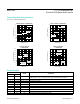
Slave Address and Input Pullup
Selection/Default Logic State
Address inputs AD0 and AD2 determine the MAX7322
slave address, select which inputs have pullup resistors
and set the default logic state for outputs. Pullups are
enabled on the input ports in groups of two (see Table 2).
The MAX7319, MAX7321, MAX7322, and MAX7323 use
a different range of slave addresses (110xxxx) than the
MAX7320 (101xxxx).
The MAX7322 slave address is determined on each I
2
C
transmission, regardless of whether the transmission
is actually addressing the MAX7322. The MAX7322
distinguishes whether address inputs AD2 and AD0 are
connected to SDA or SCL instead of fixed logic levels
V+ or GND during this transmission. This means that the
MAX7322 slave address can be configured dynamically in
the application without cycling the device supply.
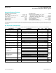
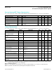
Table 1. MAX7319–MAX7329 Family Comparison (continued)
PART
I
2
C
SLAVE
ADDRESS
INPUTS
INPUT
INTERRUPT
MASK
OPEN-
DRAIN
OUTPUTS
PUSH-
PULL
OUTPUTS
I
2
C DATA
WRITE
I
2
C DATA
READ
APPLICATION
16-PORT EXPANDERS
MAX7324
101xxxx
And
110xxxx
8 Yes — 8 — —
Software equivalent to a
MAX7320 plus a MAX7319.
MAX7325 Up to 8 — Up to 8 8 — —
Software equivalent to a
MAX7320 plus a MAX7321.
MAX7326 4 Yes — 12 — —
Software equivalent to a
MAX7320 plus a MAX7322.
MAX7327 Up to 4 — Up to 4 12 — —
Software equivalent to a
MAX7320 plus a MAX7323.
www.maximintegrated.com
Maxim Integrated
│
7
MAX7322 I
2
C Port Expander with
4 Push-Pull Outputs and 4 Inputs