
Datasheet


on the 2-wire interface, or if the master in a single-master
system has an open-drain SCL output.
Each transmission consists of a START condition sent by
a master, followed by the MAX7322’s 7-bit slave address
plus R/W bit, one or more data bytes, and finally a STOP
condition (Figure 2).
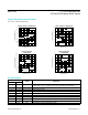
Start and Stop Conditions
Both SCL and SDA remain high when the interface is not
busy. A master signals the beginning of a transmission
with a START (S) condition by transitioning SDA from high
to low while SCL is high. When the master has finished
communicating with the slave, the master issues a STOP
(P) condition by transitioning SDA from low to high while
SCL is high. The bus is then free for another transmission
(Figure 2).
Bit Transfer
One data bit is transferred during each clock pulse.
The data on SDA must remain stable while SCL is high
(Figure 3).
Acknowledge
The acknowledge bit is a clocked 9th bit the recipient
uses to acknowledge receipt of each byte of data
(Figure 4).Each byte transferred effectively requires
9 bits. The master generates the 9th clock pulse, and the
recipient pulls down SDA during the acknowledge clock
pulse, such that the SDA line is stable low during the high
period of the clock pulse. When the master is transmitting to
the MAX7322, the MAX7322 generates the acknowledge
bit because the device is the recipient. When the MAX7322
is transmitting to the master, the master generates the
acknowledge bit because the master is the recipient.
Figure 4. Acknowledge
Figure 3. Bit Transfer
Figure 2. Start and Stop Conditions
SCL
SDA BY
TRANSMITTER
CLOCK PULSE
FOR ACKNOWLEDGMENT
START
CONDITION
SDA BY
RECEIVER
1 2 8 9
S
SDA
SCL
DATA LINE STABLE;
DATA VALID
CHANGE OF DATA
ALLOWED
SDA
SCL
START
CONDITION
STOP
CONDITION
S P
www.maximintegrated.com
Maxim Integrated
│
10
MAX7322 I
2
C Port Expander with
4 Push-Pull Outputs and 4 Inputs