
Datasheet


MAX71020
Single-Chip Electricity Meter AFE
5Maxim Integrated
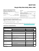
ELECTRICAL CHARACTERISTICS (continued)
Note 2: V
3P3SYS
and V
3P3A
must be connected together.
Note 3: GNDA and GNDD must be connected together.
Note 4: Guaranteed by design, not production tested.
PARAMETER CONDITIONS MIN TYP MAX UNITS
Preamplifier and ADC Total
Harmonic
(V
IN
= 28mV Differential)
T
A
= +25°C; V
V3P3A
= 3.3V, PRE_E = 1 -80 dB
Preamplifier and ADC Total
Harmonic Distortion
(V
IN
= 15mV Differential)
T
A
= +25°C; V
V3P3A
= 3.3V, PRE_E = 1 -85 dB
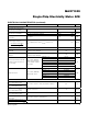
SPI SLAVE TIMING SPECIFICATIONS
SPI Setup Time SPI_DI to SPI_CK rise 10 ns
SPI Hold Time SPI_CLK rise to SPI_DI 10 ns
SPI Output Delay SPI_CLK fall to SPI_D0 40 ns
SPI Recovery Time SPI_CSZ fall to SPI_CLK 10 ns
SPI Removal Time SPI_CLK to SPI_CSZ rise 15 ns
SPI Clock High 40 ns
SPI Clock Low 40 ns
SPI Clock Frequency 10 MHz
SPI Transaction Space
(SPI_CSZ Rise to SPI_CSZ Fall)
1 µs
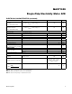
RESETZ TIMING
Reset Pulse Width
Following power-on 1 ms
At all other times 5 µs
Reset Pulse Rise Time (Note 4) 1 µs
VOLTAGE MONITOR
Nominal Value at +22°C
(VNOM)
V
V3P3A
= 3.3V 130 LSB
Voltage Measurement Equation
V
V3P3SYS
(CALC) = 3.29V +
(VSENSE – 130) x 0.025V +
STEMP x 242FV
Voltage Error
-
×
üüü
üüü
üüü
100 1
V
-4 +4 %