
Datasheet


MAX71020
Single-Chip Electricity Meter AFE
16Maxim Integrated
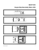
Figure 4 shows the shapes of V(t), I(t), the instantaneous
power and the accumulated energy resulting from 50
samples of the voltage and current signals over a period
of 20ms. The application of 240V AC and 100A results in
an accumulation of 480Ws (= 0.133Wh) over the 20ms
period, as indicated by the accumulated power curve. The
described sampling method works reliably, even in the
presence of dynamic phase shift and harmonic distortion.
After a sufficient number (typically 2520) of multiplexer
frames have been collected, the MAX71020 issues an
interrupt to the host using the INTZ pin, signalling that new
energy values are available.
Fault and Reset Behavior
Events at Power-Down
Power fault detection is performed by internal com-
parators that monitor the voltage at the V
3P3A
pin and
also monitor the internally generated V
DD
pin voltage
(1.8V DC). V
3P3SYS
and V
3P3A
must be connected
together at the PCB level so that the comparators, which
are internally connected only to the V
3P3A
pin, are able to
simultaneously monitor the common V
3P3SYS
and V
3P3A
voltage. The following discussion assumes that V
3P3A
and V
3P3SYS
are connected together at the PCB level.
During a power failure, as V
3P3A
falls, two thresholds are
detected. The first threshold, at 3.0V, warns the host con-
troller that the analog modules are no longer accurate.
The second threshold, at 2.8V, warns the host controller
that a serious reduction in supply voltage has occurred
and that the reliability of OTP reads may be affected.
Reset Sequence
The MAX71020 does not provide automatic reset genera-
tion. The reset needs to be generated by the host con-
troller or by external circuitry connected to the RESETZ
pin. When the MAX71020 receives a reset signal, either
from the RESETZ pin or from the SPI (using a write to
the RESET register at address 0x322), it asynchronously
halts what it was doing. It then clears the RAM and
invokes the Load Engine (LE). The LE initializes RAM and
hardware control registers from the CE code image that
is stored in OTP memory. Only RAM cells and hardware
registers that need not change dynamically are loaded.
All other RAM cells and registers have to be loaded by
the host controller. The LE automatically refreshes the
values of the registers it is tasked with loading during
the operation of the MAX71020. This refresh happens in
increments of one register at a time and at a rate of one
register per second.
An errant reset can occur during EMI events. If this hap-
pens, the host controller is notified. This is accomplished
by the holding the INTZ pin low until the host clears the
event (the F_RESET bit in the M_STAT register is set to
indicate that a reset has occurred).
Applications Information
Sensor Connection
Figure 5 to Figure 8 show voltage-sensing resistive
dividers, current-sensing current transformers (CTs) and
current-sensing resistive shunts and their proper connec-
tion to the voltage and current inputs of the MAX71020.
All input signals to the MAX71020 sensor inputs are volt-
age signals providing a scaled representation of either a
sensed voltage or current.
Figure 4. Voltage, Current, Momentary and Accumulated Energy
Table 6. VSTAT[1:0]
VSTAT[1:0] DESCRIPTION
00 System Power-OK. V
V3P3A
> 3.0V. Analog modules are functional and accurate.
01 System Power is low. 2.8V < V
V3P3A
< 3.0V. Analog modules not accurate.
11 System power below 2.8V. Ability to monitor power is about to fail.
15105
-400
-300
-200
-100
0
100
200
300
400
500
-500
02
0
CURRENT [A]
VOLTAGE [V]
ENERGY PER INTERVAL [Ws]
ACCUMULATED ENERGY [Ws]