
Datasheet


MAX71020
Single-Chip Electricity Meter AFE
12Maxim Integrated
Analog-to-Digital Converter (ADC)
A single second-order delta-sigma ADC digitizes the
voltage and current inputs to the device. The resolution
of the ADC is dependent on several factors.
Initiation of each ADC conversion is automatically con-
trolled by logic internal to the MAX71020. At the end of
each ADC conversion, the FIR filter output data is stored
into the register determined by the multiplexer selection.
FIR data is stored LSB justified, but shifted left 9 bits.
FIR Filter
The finite impulse response filter is an integral part of the
ADC and it is optimized for use with the multiplexer. The
purpose of the FIR filter is to decimate the ADC output to
the desired resolution. At the end of each ADC conver-
sion, the output data is stored into the register deter-
mined by the multiplexer selection.
Voltage References
A bandgap circuit provides the reference voltage (VREF)
to the ADC. Since the VREF bandgap amplifier is chop-
per stabilized, the DC offset voltage, which is the most
significant long-term drift mechanism in the voltage ref-
erence (VREF), is automatically removed by the chopper
circuit.
Digital Computation Engine (CE)
The CE, a dedicated 32-bit signal processor, performs
the precision computations necessary to accurately mea-
sure energy. The CE calculations and processes include:
●
Multiplication of each current sample with its associ-
ated voltage sample to obtain the energy per sample
(when multiplied with the constant sample time)
●
Frequency-insensitive delay cancellation on all four
channels (to compensate for the delay between
samples caused by the multiplexing scheme)
● 90° phase shifter (for VAR calculations)
● Pulse generation
● Monitoring of the input signal frequency (for frequency
and phase information)
● Monitoring of the input signal amplitude (for sag
detection)
●
Scaling of the processed samples based on calibra-
tion coefficients
● Scaling of samples based on temperature compensa-
tion information
● Gain and phase compensation
Meter Equations
The MAX71020 provides hardware assistance to the CE
in order to support various meter equations. This assis-
tance is controlled through registers that are controlled
by the CE code image. The CE firmware implements the
equations listed in Table 2 or a subset thereof.
Pulse Generators
The MAX71020 provides up to four pulse generators,
VPULSE, WPULSE, XPULSE, and YPULSE, as well as
hardware support for the VPULSE and WPULSE pulse
generators. The pulse generators are used to output CE
status indicators and energy usage. See Table 3.
The polarity of the pulses may be inverted with control bit
PLS_INV. When this bit is set, the pulses are active-high,
rather than the more usual active-low. PLS_INV inverts all
four pulse outputs.
The function of each pulse generator is determined by
the CE code. Standard configurations of the MAX71020
provide a mains zero-crossing indication on XPULSE and
voltage sag detection on YPULSE.
A common use of the zero-crossing pulses is to gener-
ate interrupts in order to drive RTC software in places
where the mains frequency is sufficiently accurate to do
so and also to adjust for crystal aging. Zero-crossing can
also be used to control PLC modems or cut-off relays. A
common use for the SAG pulse is to generate an interrupt
that alerts the host controller when mains power is about
to fail, so that the host controller can store accumulated
energy and other data to EEPROM before the board sup-
ply voltage drops below safe levels.
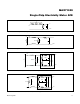
Table 2. Inputs Selected in Multiplexer Cycles
EQU DESCRIPTION
Wh AND VARh FORMULA
ELEMENT 0 ELEMENT 1
0
1 element, 2W, 1j with neutral current sense
VA ∙ IA VA ∙ IB
1
1 element, 3-W, 1j
VA(IA-IB)/2 VA ∙ IB/2
2 2 element, 3-W VA ∙ IA VB ∙ IB