
Datasheet


Computing Power Dissipation
The upper limit for power dissipation (P
D
) for the
MAX6979 is determined from the following equation:
P
D
= (V+ x I+) + (V
OUT
x DUTY x I
OUT
x N)
where:
V+ = supply voltage
I+ = operating supply current when sinking I
OUT
LED
drive current into N outputs
DUTY = PWM duty cycle applied to OE
N = number of MAX6979 outputs driving LEDs at the
same time (maximum is 16)
V
OUT
= MAX6979 port output voltage when driving load
LED(s)
I
OUT
= LED drive current programmed by R
SET
P
D
= power dissipation, in mW if currents are in mA
Dissipation example:
I
OUT
= 47mA, N = 16, DUTY = 1,
V
OUT
= 2V, V+ = 5.25V
P
D
= (5.25V x 25mA) + (2V x 1 x 47mA x 16) = 1.776W
Thus, for a 24-pin TSSOP package (T
JA
= 1/0.0122 =
+82°C/W from the
Absolute Maximum Ratings
), the
maximum allowed ambient temperature T
A
is given by:
T
J(MAX)
= T
A
+ (P
D
x T
JA
) = +150°C =
T
A
+ (1.776 x 82°C/W)
so T
A
= +145.6°C.
Overtemperature Cutoff
The MAX6979 contains an internal temperature sensor
that turns off all outputs when the die temperature
exceeds approximately +165°C. The outputs are
enabled again when the die temperature drops below
approximately +140°C. Register contents are not
affected, so when a driver is overdissipating, the exter-
nal symptom is the load LEDs cycling between on and
off as the driver repeatedly overheats and cools, alter-
nately turning the LEDs off and then back on again.
Power-Supply Considerations
The MAX6979 operates with a chip supply V+, and one
or more LED supplies. Bypass each supply to GND
with a 0.1µF capacitor as close to the MAX6979 as pos-
sible. This is normally adequate for static LED driving.
For multiplex or PWM applications, it is necessary to
add an additional bulk electrolytic capacitor of 4.7µF or
more to each supply for every 4 to 16 MAX6979s. The
necessary capacitance depends on the LED load cur-
rent, PWM switching frequency, and serial interface
speed. Inadequate V+ decoupling can cause timing
problems, and very noisy LED supplies can affect LED
current regulation.
MAX6979
16-Port, 5.5V Constant-Current LED Driver with
LED Fault Detection and Watchdog
_______________________________________________________________________________________ 9
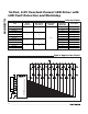
L = Low-logic level; H = High-logic level; X = Don’t care; P = Present state; R = Previous state
SHIFT-REGISTER
CONTENTS
LATCH CONTENTS OUTPUT CONTENTS
SERIAL
DATA
INPUT
DIN
CLOCK
INPUT
CLK
D
0
D
1
D
2
…D
n-1
D
n
LOAD
INPUT
LE
D
0
D
1
D
2
…D
n-1
D
n
BLANKING
INPUT
OE
D
0
D
1
D
2
…D
n-1
D
n
HHR
1
R
2
…R
n-2
R
n-1
—
——————
— — —————
LLR
1
R
2
…R
n-2
R
n-1
—
——————
— — —————
XR
0
R
1
R
2
…R
n-1
R
n
—
——————
— — —————
——
XXX…XX H
R
0
R
1
R
2
—R
n-1
R
n
— — —————
——P
1
P
2
P
3
…P
n-1
P
n
L
P
0
P
1
P
2
…P
n-1
P
n
L P
0
P
1
P
2
… P
n-1
P
n
— — —————— —
XXX…XX
H Hi-Z Hi-Z Hi-Z … Hi-Z Hi-Z
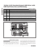
Table 1. 4-Wire Serial-Interface Truth Table