
Datasheet

MAX6965
9-Output LED Driver with Intensity Control
and Hot-Insertion Protection
______________________________________________________________________________________ 17
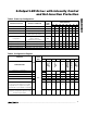
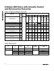
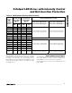
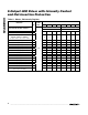
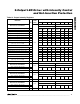
Table 10. PWM Intensity Settings (Blink Enabled)
EXAMPLES OF LED BLINK BEHAVIOR
(LED IS ON WHEN OUTPUT IS LOW)
PWM DUTY
CYCLE OUTPUT
BLINK PHASE X
REGISTER
BIT = 0
PWM DUTY
CYCLE OUTPUT
BLINK PHASE X
REGISTER
BIT = 1
OUTPUT
(OR
GLOBAL)
INTENSITY
SETTING
LOW
TIME
HIGH
TIME
LOW
TIME
HIGH
TIME
B L I N K PH A SE 0 R EG IST ER B IT = 0
B L I N K PH A SE 1 R EG IST ER B IT = 1
B L I N K PH A SE 0 R EG IST ER B IT = 1
B L I N K PH A SE 1 R EG IST ER B IT = 0
0x0 1/16
15/16
15/16 1/16
0x1 2/16
14/16
14/16 2/16
0x2 3/16
13/16
13/16 3/16
0x3 4/16
12/16
12/16 4/16
0x4 5/16
11/16
11/16 5/16
0x5 6/16
10/16
10/16 6/16
0x6 7/16
9/16
9/16 7/16
P hase 0: LE D on at l ow i ntensi ty
P hase 1: LE D on at hi g h i ntensi ty
P hase 0: LE D on at hi g h i ntensi ty
P hase 1: LE D on at l ow i ntensi ty
0x7 8/16
8/16
8/16 8/16 Output is half intensity during both blink phases
0x8 9/16
7/16
7/16 9/16
0x9
10/16 6/16
6/16 10/16
0xA
11/16 5/16
5/16 11/16
0xB
12/16 4/16
4/16 12/16
0xC
13/16 3/16
3/16 13/16
0xD
14/16 2/16
2/16 14/16
0xE
15/16 1/16
1/16 15/16
P hase 0: LE D on at hi g h i ntensi ty
P hase 1: LE D on at l ow i ntensi ty
P hase 0: LE D on at l ow i ntensi ty
P hase 1: LE D on at hi g h i ntensi ty
0xF
Static
low
Static
low
Static high
impedance
Static high
impedance
Phase 0: LED on continuously
Phase 1: LED off continuously
Phase 0: LED off continuously
Phase 1: LED on continuously
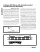
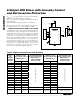
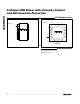
The MAX6965 must be protected from the negative
voltage transient generated when switching off induc-
tive loads, such as relays, by connecting a reverse-
biased diode across the inductive load (Figure 19). The
peak current through the diode is the inductive load’s
operating current.
Power-Supply Considerations
The MAX6965 operates with a power-supply voltage of
2V to 3.6V. Bypass the power supply to GND with at
least 0.047µF as close to the device as possible.
For the QFN version, connect to the underside exposed
pad to GND.