
Datasheet

MAX6960–MAX6963
4-Wire Serially Interfaced
8 x 8 Matrix Graphic LED Drivers
27
Maxim Integrated
REGISTER DATA
REGISTER
ADDRESS
CODE
(HEX)
D7 D6 D5 D4 D3 D2 D1 D0
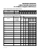
Fault (read) 0x05
Fault
flag
Part ID X X OT flag
Short
flag
Open
flag
Fault (write) clears fault register status 0x05 0 Part ID X X 0 0 0
Device is MAX6960 0x05 X 0 0 X X X X X
Device is MAX6961 0x05 X 0 1 X X X X X
Device is MAX6962 0x05 X 1 0 X X X X X
Device is MAX6963 0x05 X 1 1 X X X X X
No LED or OT faults 0x05 0 Part ID X X 0 0 0
At least one open-circuit LED fault 0x05 1 Part ID X X X X 1
At least one short-circuit LED fault 0x05 1 Part ID X X X 1 X
Overtemperature fault 0x05 1 Part ID X X 1 X X
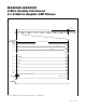
Table 32. Fault and Device ID Register Format
REGISTER DATA
ACTION
ADDRESS
CODE (HEX)
D7 D6 D5 D4 D3 D2 D1 D0
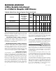
GLOBAL CLEAR PLANES 0x0C
GREEN
P3
GREEN
P2
GREEN
P1
GREEN
P0
RED P3 RED P2 RED P1 RED P0
Clear all red plane P0
display memory
0x0C X XXXXXX1
Clear all red plane P1
display memory
0x0C X XXXXX1X
Clear all red plane P2
display memory*
0x0C X XXXX1XX
Clear all red plane P3
display memory*
0x0C X X X X 1 X X X
Clear all green plane P0
display memory
†
0x0C X X X 1 X X X X
Clear all green plane P1
display memory
†
0x0C X X 1 XXXXX
Clear all green plane P2
display memory
†*
0x0C X 1 XXXXXX
Clear all green plane P3
display memory
†*
0x0C 1 XXXXXXX
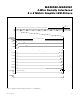
Table 31. Global Clear Planes Register Format
*
These bit settings are ignored when the global panel configuration register bit PI is clear (i.e., ignored in 2-bits-per-pixel mode).
†
These bit settings are ignored when the global panel configuration register bit C is clear (i.e., ignored in monocolor mode).