
Datasheet


to read. Bits D7 to D0 contain dummy data, which is
discarded.
4) Take CS high (while CLK is still high after clocking
in the last data bit), positions D7 through D0 in the
shift register are now loaded with the register data
addressed by bits D15 through D8.
5) Take CLK low.
6) Issue another read or write command (which can
be a no-op), and examine the bit stream at DOUT;
the second 8 bits are the contents of the register
addressed by bits D14 through D8 in step 3.
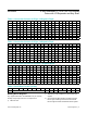
Digit Type Registers
The MAX6954 uses 32 digit registers to store the char-
acters that the user wishes to display. These digit regis-
ters are implemented with two planes, P0 and P1. Each
digit is represented by 2 bytes of memory, 1 byte in
plane P0 and the other in plane P1. The digit registers
are mapped so that a digit’s data can be updated in
plane P0, plane P1, or both planes at the same time
(Table 6).
If the blink function is disabled through the Blink Enable
Bit E (Table 19) in the configuration register, then the
digit register data in plane P0 is used to multiplex the
display. The digit register data in P1 is not used. If the
blink function is enabled, then the digit register data in
both plane P0 and plane P1 are alternately used to mul-
tiplex the display. Blinking is achieved by multiplexing
the LED display using data plane P0 and plane P1 on
alternate phases of the blink clock (Table 20).
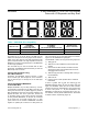
The data in the digit registers does not control the digit
segments directly for 14- and 16-segment displays.
Instead, the register data is used to address a charac-
ter generator that stores the data for the 14- and 16-
segment fonts (Tables 7 and 8). The lower 7 bits of the
digit data (D6 to D0) select the character from the font.
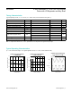
Figure 3. Timing Diagram
Figure 2. MAX6954 Daisy-Chain Connection
t
CSS
t
CL
t
CH
t
CP
t
CSH
t
CSW
t
DS
t
DH
D15
CLK
DIN
CS
D14 D1 D0
D15
t
DO
DOUT
MAX6954
DOUT
MICROCONTROLLER
CLK
DIN
MAX6954 MAX6954
CLK
DIN
CS
DOUT
CLK
DIN
CS
DOUT
CLK
DIN
CS
DOUT
CS
www.maximintegrated.com
Maxim Integrated
│
9
MAX6954 4-Wire Interfaced, 2.7V to 5.5V LED Display
Driver with I/O Expander and Key Scan