
Datasheet

*7-segment digits can be replaced by directly controlled discrete LEDs according to settings in the decode mode register (Table 11).
**The highlighted row is used in Typical Operating Circuit 1 for display digits 6 and 7.
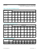
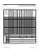
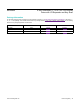
Table 40. Slot 4 Configuration
CONFIGURATION
CHOICE
Common-Cathode
Drive: Digit Type
CC6: 16-seg monocolor
CC7: 16-seg monocolor
CC6 and CC7:
(2) 7-seg bicolor
or (4) 7-seg monocolor
or (1) 7-seg bicolor
and (2) 7-seg monocolor*
CC6 and CC7:
(1)16-seg bicolor
CC6: 16-seg monocolor
CC6: (2) 7-seg monocolor*
or 7-seg bicolor
CC7: 14-seg monocolor
CC6: 14-seg monocolor
CC7: 16-seg monocolor
CC7: (2) 7-seg monocolor*
or 7-seg bicolor
CC6 and CC7: (2) 14-seg
monocolor or 14-seg
bicolor
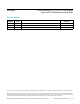
00 a1 a1 1a a1 a1 1a a a a1 1a a
01 a2 a2 — a2 a2 — — — a2 — —
02 b b 1b b b 1b b b b 1b b
03 c c 1c c c 1c c c c 1c c
04 d1 d1 1d d1 d1 1d d d d1 1d d
05 d2 d2 1dp d2 d2 1dp — — d2 1dp —
06 CC6 — CC6 CC6 CC6 CC6 — CC6 — — CC6
07 — CC7 CC7 CC7 — — CC7 — CC7 CC7 CC7
08 e e 1e e e 1e e e e 1e e
09 f f 1f f f 1f f f f 1f f
010 g1 g1 1g g1 g1 1g g1 g1 g1 1g g1
011 g2 g2 2a g2 g2 2a g2 g2 g2 2a g2
012 h h 2b h h 2b h h h 2b h
013 i i 2c i i 2c i i i 2c i
014 j j 2d j j 2d j j j 2d j
015 k k 2e k k 2e k k k 2e k
016 l l 2f l l 2f l l l 2f l
017 m m 2g m m 2g m m m 2g m
018 dp dp 2dp dp dp 2dp dp dp dp 2dp dp
ADDRESS CODE
(HEX)
0x0C
REGISTER DATA
D7 0 1 0 1
D6 0 0 1 1
D5
See Table 39.
D4
D3
See Table 38.
D2
D1
See Table 37.
D0
www.maximintegrated.com
Maxim Integrated
│
34
MAX6954 4-Wire Interfaced, 2.7V to 5.5V LED Display
Driver with I/O Expander and Key Scan