
Datasheet


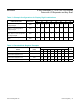
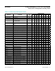
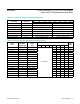
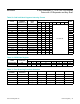

Table 33. Key Mask Register Format
Table 32. Port Configuration Register Format
KEY
MASK
REGISTER
ADDRESS
CODE
(HEX
REGISTER DATA
WITH APPROPRIATE SWITCH NAMED BELOW
D7 D6 D5 D4 D3 D2 D1 D0
Key_A Mask
Register
0x08 SW_A7 SW_A6 SW_A5 SW_A4 SW_A3 SW_A2 SW_A1 SW_A0
Key_B Mask
Register
0x09 SW_B7 SW_B6 SW_B5 SW_B4 SW_B3 SW_B2 SW_B1 SW_B0
Key_C Mask
Register
0x0A SW_C7 SW_C6 SW_C5 SW_C4 SW_C3 SW_C2 SW_C1 SW_C0
Key_D Mask
Register
0x0B SW_ D7 SW_D6 SW_D5 SW_D4 SW_D3 SW_D2 SW_D1 SW_D0
MODE
ADDRESS
CODE (HEX)
REGISTER DATA
D7 D6 D5 D4 D3 D2 D1 D0
GPIO
Configuration
Register
0x06 Set number of keys scanned
Set port direction for ports P0 to P4:
0 = output, 1 = input
PORT ALLOCATION OPTIONS
0 Keys Scanned 0x06 0 0 0 P4 P3 P2 P1 P0
8 Keys Scanned 0x06 0 0 1 IRQ P3 P2 P1 Key_A
16 Keys Scanned 0x06 0 1 0 IRQ P3 P2 Key_B Key_A
24 Keys Scanned 0x06 0 1 1 IRQ P3 Key_C Key_B Key_A
32 Keys Scanned 0x06 1 X X IRQ Key_D Key_C Key_B Key_A
EXAMPLE PORT CONFIGURATION SETTINGS
No Keys
Scanned, P4 and
P2 Are Outputs,
Others Are Inputs
0x06 0 0 0 0 1 0 1 1
8 Keys Scanned,
P3 and P1 Are
Outputs, P2 Is an
Input
0x06 0 0 1 X 0 1 0 X
32 Keys
Scanned, No
GPIO Ports
0x06 1 X X X X X X X
www.maximintegrated.com
Maxim Integrated
│
29
MAX6954 4-Wire Interfaced, 2.7V to 5.5V LED Display
Driver with I/O Expander and Key Scan