
Datasheet


(Voltage with respect to GND.)
V+ ........................................................................-0.3V to +6V
All Other Pins...........................................-0.3V to (V+ + 0.3V)
Current
O0–O7 Sink Current ..................................................... 935mA
O0–O18 Source Current.................................................55mA
DIN, CLK, CS, OSC, DOUT, BLINK, OSC_OUT, ISET .. 20mA
P0, P1, P2, P3, P4 .........................................................40mA
GND ..................................................................................... 1A
Continuous Power Dissipation (T
A
= +70°C)
36-Pin SSOP (derate at 11.8mW/°C above +70°C) ....941mW
40-Pin PDIP (derate at 16.7mW/°C above +70°C) ...1333mW
40-Pin TQFN (derate at 37mW/°C above +70°C) .....2963mW
Operating Temperature Range
(T
MIN
to T
MAX
) ............................................. -40°C to +125°C
Junction Temperature ...................................................... +150°C
Storage Temperature Range ............................ -65°C to +150°C
Lead Temperature (soldering, 10s) .................................+300°C
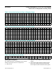
(Typical Operating Circuits, V+ = 2.7V to 5.5V, T
A
= T
MIN
to T
MAX
, unless otherwise noted.) (Note 1)
PARAMETER SYMBOL CONDITIONS MIN TYP MAX UNITS
Operating Supply Voltage V+ 2.7 5.5 V
Shutdown Supply Current I
SHDN
Shutdown mode, all
digital inputs at V+
or GND
T
A
= +25°C 10 35
µA
T
A
= T
MIN
to T
MAX
40
Operating Supply Current I+
All segments on, all
digits scanned,
intensity set to full,
internal oscillator,
DOUT open circuit,
no display or
OSC_OUT load
connected
T
A
= +25°C 22 30
mA
T
A
= T
MIN
to T
MAX
35
Master Clock Frequency f
OSC
OSC = RC oscillator, R
SET
= 56kW,
C
SET
= 22pF, V+ = 3.3V
4
MHz
OSC driven externally 1 8
Dead Clock Protection Frequency f
OSC
95 kHz
OSC Internal/External Detection
Threshold
V
OSC
1.7 V
OSC High Time t
CH
50 ns
OSC Low Time t
CL
50 ns
Slow Segment Blink Period f
SLOWBLINK
OSC = RC oscillator, R
SET
= 56kW,
C
SET
= 22pF, V+ = 3.3V
1 s
Fast Segment Blink Period f
FASTBLINK
OSC = RC oscillator, R
SET
= 56kW,
C
SET
= 22pF, V+ = 3.3V
0.5 s
Fast or Slow Segment Blink Duty
Cycle
49.5 50.5 %
www.maximintegrated.com
Maxim Integrated
│
2
MAX6954 4-Wire Interfaced, 2.7V to 5.5V LED Display
Driver with I/O Expander and Key Scan
DC Electrical Characteristics
Stresses beyond those listed under “Absolute Maximum Ratings” may cause permanent damage to the device. These are stress ratings only, and functional operation of the device at these
or any other conditions beyond those indicated in the operational sections of the specifications is not implied. Exposure to absolute maximum rating conditions for extended periods may affect
device reliability.
Absolute Maximum Ratings