
Datasheet
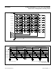


The timing in Figure 8 loops over time, with 32 keys
experiencing a full key-scanning debounce over typi-
cally 25.6ms. Four keys are sampled every 1.6ms, or
every multiplex cycle. If at least one key that was not
previously pressed is found to have been pressed dur-
ing both sampling periods, then that key press is
debounced, and an interrupt is issued. The key-scan
circuit detects any combination of keys being pressed
during each debounce cycle (n-key rollover).
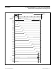
Port Conguration Register
The port configuration register selects how the five port
pins are used. The port configuration register format is
described in Table 32.
Key Mask Registers
The Key_A Mask, Key_B Mask, Key_C Mask, and
Key_D Mask write-only registers (Table 33) configure
the key-scanning circuit to cause an interrupt only when
selected (masked) keys have been debounced. Each bit
in the register corresponds to one key switch. The bit is
clear to disable interrupt for the switch, and set to enable
interrupt. Keys are always scanned (if enabled through
the port configuration register), regardless of the setting
of these interrupt bits, and the key status is stored in the
appropriate Key_x pressed register.
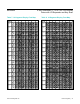
Key Debounced Registers
The Key_A debounced, Key_B debounced, Key_C
debounced, and Key_D debounced read-only registers
(Table 34) show which keys have been detected as
debounced by the key-scanning circuit.
Each bit in the register corresponds to one key switch. The
bit is set if the switch has been correctly debounced since
the register was read last. Reading a debounced register
clears that register (after the data has been read) so that
future keys pressed can be identified. If the debounced
registers are not read, the key-scan data accumulates.
However, as there is no FIFO in the MAX6954, the user
is not able to determine key order, or whether a key has
been pressed more than once, unless the debounced key
status registers are read after each interrupt, and before
the next key-scan cycle.
Reading any of the four debounced registers clears the
IRQ output. If a key is pressed and held down, the key is
reported as debounced (and IRQ issued) only once.
The key must be detected as released by the key-scan-
ning circuit, before it debounces again. If the
debounced registers are being read in response to the
IRQ being asserted, then the user should generally read
all four registers to ensure that all the keys that were
detected by the key-scanning circuit are discovered.
Key Pressed Registers
The Key_A pressed, Key_B pressed, Key_C pressed and
Key_D pressed read-only registers (Table 35)show which
keys have been detected as pressed by the key-scanning
circuit during the last test.
Each bit in the register corresponds to one key switch.
The bit is set if the switch has been detected as
pressed by the key-scanning circuit during the last test.
Note: Unused register bits read as zero.
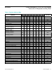
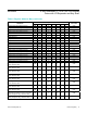
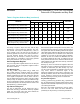
Table 6. Register Address Map (continued)
REGISTER
ADDRESS (COMMAND BYTE)
HEX CODE
D15 D14 D13 D12 D11 D10 D9 D8
Write Digit 2a Planes P0 and P1 with Same
Data (7 Segment Only), Reads as 0x00
R/W 1 1 0 1 0 1 0 0x6A
Write Digit 3a Planes P0 and P1 with Same
Data (7 Segment Only), Reads as 0x00
R/W 1 1 0 1 0 1 1 0x6B
Write Digit 4a Planes P0 and P1 with Same
Data (7 Segment Only), Reads as 0x00
R/W 1 1 0 1 1 0 0 0x6C
Write Digit 5a Planes P0 and P1 with Same
Data (7 Segment Only), Reads as 0x00
R/W 1 1 0 1 1 0 1 0x6D
Write Digit 6a Planes P0 and P1 with Same
Data (7 Segment Only), Reads as 0x00
R/W 1 1 0 1 1 1 0 0x6E
Write Digit 7a Planes P0 and P1 with Same
Data (7 Segment Only), Reads as 0x00
R/W 1 1 0 1 1 1 1 0x6F
www.maximintegrated.com
Maxim Integrated
│
15
MAX6954 4-Wire Interfaced, 2.7V to 5.5V LED Display
Driver with I/O Expander and Key Scan