
Datasheet
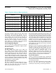


Scan-Limit Register
The scan-limit register sets how many 14-segment digits
or 16-segment digits or pairs of 7-segment digits are
displayed, from 1 to 8. A bicolor digit is connected as two
monocolor digits. The scan register also limits the number
of keys that can be scanned.
Since the number of scanned digits affects the display
brightness, the scan-limit register should not be used to
blank portions of the display (such as leading-zero sup-
pression). Table 25 shows the scan-limit register format.
Intensity Registers
Digital control of display brightness is provided and can
be managed in one of two ways: globally or individually.
Global control adjusts all digits together. Individual control
adjusts the digits separately.
The default method is global brightness control, which
is selected by clearing the global intensity bit (I data bit
D6) in the configuration register. This brightness setting
applies to all display digits. The pulse-width modulator is
then set by the lower nibble of the global intensity reg-
ister, address 0x02. The modulator scales the average
segment current in 16 steps from a maximum of 15/16
down to 1/16 of the peak current. The minimum interdigit
blanking time is set to 1/16 of a cycle. When using bicolor
digits, 256 color/brightness combinations are available.
Individual brightness control is selected by setting the
global intensity bit (I data bit D6) in the configuration reg-
ister. The pulse-width modulator is now no longer set by
the lower nibble of the global intensity register, address
0x02, and the data is ignored. Individual digital control of
display brightness is now provided by a separate pulse-
width modulator setting for each digit. Each digit is con-
trolled by a nibble of one of the four intensity registers:
intensity10, intensity32, intensity54, and intensity76 for
all display types, plus intensity10a, intensity32a, intensi-
ty54a, and intensity76a for the extra eight digits possible
when 7-segment displays are used. The data from the
relevant register is used for each digit as it is multiplexed.
The modulator scales the average segment current in 16
steps in exactly the same way as global intensity adjust-
ment.
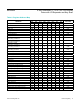
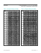
Table 26 shows the global intensity register format, Table
27 shows individual segment intensity registers, Table 28
is the even individual segment intensity format, and Table
29 is the odd individual segment intensity format.
GPIO and Key Scanning
The MAX6954 feature five general-purpose input/output
(GPIO) ports: P0 to P4. These ports can be individual-
ly enabled as logic inputs or open-drain logic outputs.
The GPIO ports are not debounced when configured as
inputs. The ports can be read and the outputs set using
the 4-wire interface.
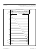
Some or all of the five ports can be configured to per-
form key scanning of up to 32 keys. Ports P0 to P4
are renamed Key_A, Key_B, Key_C, Key_D, and IRQ,
respectively, when used for key scanning. The full
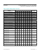
key-scanning configuration is shown in Figure 7. Table 30
is the GPIO data register.
One diode is required per key switch. These diodes can
be common-anode dual diodes in SOT23 packages, such
as the BAW56. Sixteen diodes would be required for the
maximum 32-key configuration.
The MAX6954 can only scan the maximum 32 keys if the
scan-limit register is set to scan the maximum eight digits.
If the MAX6954 is driving fewer digits, then a maximum of
(4 x n) switches can be scanned, where n is the number
of digits set in the scan-limit register. For example, if the
MAX6954 is driving four 14-segment digits cathode driv-
ers O0 to O3 are used. Only 16 keys can be scanned in
this configuration; the switches shown connected to O4
through O7 are not read.
If the user wishes to scan fewer than 32 keys, then
fewer scan lines can be configured for key scanning. The
unused Key_x ports are released back to their original
GPIO functionality. If key scanning is enabled, regardless
of the number of keys being scanned, P4 is always con-
figured as IRQ (Table 31).
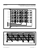
The key-scanning circuit utilizes the LEDs’ common-cath-
ode driver outputs as the key-scan drivers. O0 to 07
go low for nominally 200µs (with OSC = 4MHz) in turn
as the displays are multiplexed. By varying the oscilla-
tor frequency, the debounce time changes, though key
scanning still functions. Key_x inputs have internal pullup
resistors that allow the key condition to be tested. The
Key_x input is low during the appropriate digit multiplex
period when the key is pressed. The timing diagram of
Figure 8 shows the normal situation where all eight LED
cathode drivers are used.
www.maximintegrated.com
Maxim Integrated
│
12
MAX6954 4-Wire Interfaced, 2.7V to 5.5V LED Display
Driver with I/O Expander and Key Scan