
Datasheet


dedicated to this function though, as it is completely
separate from the rest of the circuitry. The external volt-
age divider drives PFI to sense the unregulated DC input
to the +5V regulator (see Typical Operating Circuit). The
voltage-divider ratio can be chosen such that the voltage
at PFI falls below 1.25V just before the +5V regulator
drops out. PFO then triggers an interrupt which signals
the μP to prepare for power-down.
To conserve backup-battery power, the power-fail
detector comparator is turned off and PFO is forced low
when V
BATT
connects to V
OUT
.
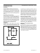
Backup-Battery Switchover
In the event of a brownout or power failure, it may be
necessary to preserve the contents of RAM. With a back-
up battery installed at V
BATT
, the devices automatically
switch RAM to backup power when V
CC
fails.
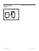
As long as V
CC
exceeds the reset threshold, V
OUT
connects to V
CC
through a 5Ω PMOS power switch.
Once VCC falls below the reset threshold, V
CC
or V
BATT
(whichever is higher) switches to V
OUT
. Unlike the
MAX690/MAX692, the MAX690A/MAX692A/MAX802L/
MAX802M/MAX805L don’t always connect V
BATT
to
V
OUT
when V
BATT
is greater than V
CC
. V
BATT
connects
to V
OUT
(through an 80Ω switch) only when V
CC
is below
the reset threshold and V
BATT
is greater than V
CC
.
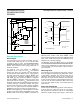
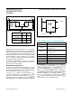
When V
CC
exceeds the reset threshold, it is connected to
the MAX690A/MAX692A/MAX802L/MAX802M/MAX805L
substrate, regardless of the voltage applied to V
BATT
(Figure 3). During this time, the diode (D1) between
V
BATT
and the substrate will conduct current from V
BATT
to V
CC
if V
BATT
is 0.6V or greater than V
CC
.
Figure 3. Backup-Battery Switchover Block Diagram
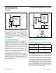
Figure 4. Using a SuperCap as a Backup Power Source with a
MAX690A/MAX802L/MAX805L and a +5V ±5% Supply
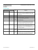
Table 1. Wiper Position and Attenuation
SIGNAL STATUS
V
CC
Disconnected from V
OUT
V
OUT
Connected to V
BATT
through an internal
80Ω PMOS switch
V
BATT
Connected to V
OUT
. Current drawn from
the battery is less than 1μA, as long as
V
CC
< V
BATT
- 1V.
PFI Power-fail comparator is disabled.
PFO Logic low
RESET Logic low
RESET Logic high (MAX805L only)
WDI Watchdog timer is disabled
SW1/SW2
SW3/SW4CONDITION
V
CC
> Reset Threshold Open
Closed
Closed
Open
Open
Closed
V
CC
< Reset Threshold and
V
CC
> V
BATT
V
CC
< Reset Threshold and
V
CC
< V
BATT
RESET THRESHOLD = 4.65V IN MAX690A/MAX802L/MAX805L.
RESET THRESHOLD = 4.4V IN MAX692A/MAX802M
V
OUT
D3
SUBSTRATE
D1
D2
SW2
SW1
SW4
SW3
V
BATT
V
CC
MAX690A
MAX692A
MAX802L
MAX802M
MAX805L
V
BATT
V
CC
V
OUT
RESET
(RESET)
GND
TO STATIC RAM
TO µP
0.1F
MAX690A
MAX802L
MAX805L
+5V
+
( ) ARE FOR MAX805L ONLY.
MAX690A/MAX692A/
MAX802L/MAX802M/
MAX805L
Microprocessor Supervisory Circuits
www.maximintegrated.com
Maxim Integrated
│
7