
Datasheet


Detailed Description
Reset Output
A microprocessor’s (μP’s) reset input starts the μP in
a known state. When the μP is in an unknown state,
it should be held in reset. The MAX690A/MAX692A/
MAX802L/MAX802M assert reset during power-up and
prevent code execution errors during power-down or
brownout conditions.
On power-up, once V
CC
reaches 1V, RESET is
guaranteed to be a logic low. As V
CC
rises, RESET
remains low. When V
CC
exceeds the reset threshold,
an internal timer keeps RESET low for a time equal to
the reset pulse width; after this interval, RESET goes
high (Figure 2). If a brownout condition occurs (if V
CC
dips below the reset threshold), RESET is triggered.
Each time RESET is triggered, it stays low for the reset
pulse width interval. Any time V
CC
goes below the reset
threshold, the internal timer restarts the pulse. If a brownout
condition interrupts a previously initiated reset pulse,
the reset pulse continues for another 200ms. On power-
down, once V
CC
goes below the threshold, RESET is
guaranteed to be logic low until V
CC
droops below 1V.
RESET is also triggered by a watchdog timeout. If a high
or low is continuously applied to the WDI pin for 1.6sec,
RESET pulses low. As long as RESET is asserted, the
watchdog timer remains clear. When RESET comes
high, the watchdog resumes timing and must be serviced
within 1.6sec. If WDI is tied high or low, a RESET pulse is
triggered every 1.8s (t
WD
plus t
RS
).
The MAX805L active-high RESET output is the inverse
of the MAX690A/MAX692A/MAX802L/MAX802M RESET
output, and is guaranteed to be valid with V
CC
down to
1.1V. Some μPs, such as Intel’s 80C51, require an active-
high reset pulse.
Watchdog Input
The watchdog circuit monitors the μP’s activity. If the μP
does not toggle the watchdog input (WDI) within 1.6sec,
a reset pulse is triggered. The internal 1.6sec timer is
cleared by either a reset pulse or by open circuiting the
WDI input. As long as reset is asserted or the WDI input
is open circuited, the timer remains cleared and does not
count. As soon as reset is released or WDI is driven high
or low, the timer starts counting. It can detect pulses as
short as 50ns.
Power-Fail Comparator
The PFI input is compared to an internal 1.25V reference.
If PFI is less than 1.25V, PFO goes low. The power-
fail comparator is intended for use as an undervoltage
detector to signal a failing power supply; it need not be
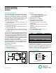
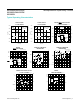
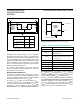
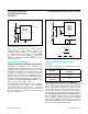
Figure 1. Block Diagram Figure 2. Timing Diagram
0.8V
WATCHDOG
TIMER
PFO
RESET
(RESET)
V
OUT
RESET
GENERATOR
BATTERY-SWITCHOVER
CIRCUITRY
1.25V
3.5V
V
BATT
V
CC
PFI
WDI
MAX690A
MAX692A
MAX802L
MAX802M
MAX805L
( ) ARE FOR MAX805L ONLY.
GND
1.25V
t
RS
+5V
0V
V
CC
0V
+5V
0V
RESET
+5V
0V
(RESET)
3.0V
3.0V
V
OUT
+5V
0V
PFO
V
BATT
= PFI = 3.0V
I
OUT
= 0mA
( ) ARE FOR MAX805L ONLY.
MAX690A/MAX692A/
MAX802L/MAX802M/
MAX805L
Microprocessor Supervisory Circuits
www.maximintegrated.com
Maxim Integrated
│
6