
Manual

assert the OC output.
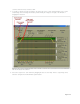
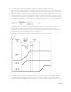
13. The Reset Timer setting determines the RESET pulse width. Set the Reset Timer to a value that is
guaranteed to reset the microprocessor connected to the pin.
14. Once all parameters are set, write them to the MAX6876 EEPROM by selecting System→Commit
Configuration to EEPROM.
15. The configuration can be saved to a file by selecting System→Save Configuration. All of the registers are
written to this configuration file.
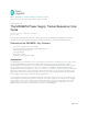
Multiple MAX6876 devices can be connected together for more than 4 channels, but this multiple-device
configuration only operates in tracking mode, in which all channels ramp-up at once. See the datasheet for
more information and an application circuit for connecting multiple MAX6876 devices.
Related Parts
MAX6876 EEPROM-Programmable, Quad, Power-Supply
Tracker/Sequencer Circuit
Free Samples
More Information
For Technical Support: http://www.maximintegrated.com/support
For Samples: http://www.maximintegrated.com/samples
Other Questions
and Comments:
http://www.maximintegrated.com/contact
Application Note
3917: http://www.maximintegrated.com/an3917
USER GUIDE 3917, AN3917, AN 3917, APP3917, Appnote3917, Appnote 3917
Copyright © by Maxim Integrated Products
Additional Legal Notices:
http://www.maximintegrated.com/legal
Page 6 of 6