
Datasheet
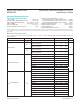
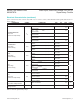
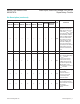
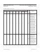
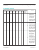

PIN
NAME FUNCTION
MAX6715A/
MAX6716A
MAX6717A/
MAX6718A
MAX6719A/
MAX6720A
MAX6721A/
MAX6722A
MAX6723A/
MAX6724A
MAX6725A/
MAX6726A
MAX6727A
MAX6728A/
MAX6729A/
MAX6797A
5 — — — — — — — RST2
Active-Low Reset Output,
Open-Drain or Push-Pull.
RST2 changes from high
to low when V
CC1
or V
CC2
drops below the selected
reset thresholds or MR is
pulled low. RST2 remains
low for the reset timeout
period after V
CC1
/V
CC2
exceed the device reset
thresholds or MR goes
low to high. Open-drain
outputs require an external
pullup resistor. Push-pull
outputs are referenced to
V
CC2
.
2 2 2 2 2 2 2 2 GND Ground
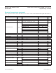
3 3 3 3 — 5 5 5 MR
Active-Low Manual-Reset
Input. Internal 50kΩ pullup
to V
CC1
. Pull low
to force a reset. Reset
remains active as long
as MR is low and for the
reset timeout period after
MR goes high. Leave
unconnected or connect to
V
CC1
if unused.
4 4 4 4 4 6 6 6 V
CC2
Secondary Supply Voltage
Input. Powers
the device when it is
above V
CC1
and input
for secondary reset
threshold monitor.
6 5 6 6 6 8 8 8 V
CC1
Primary Supply Voltage
Input. Powers the device
when it is above V
CC2
and
input for prim
ary reset threshold
monitor.
MAX6715A–MAX6729A/
MAX6797A
Dual/Triple, Ultra-Low-Voltage, SOT23 μP
Supervisory Circuits
www.maximintegrated.com
Maxim Integrated
│
7
Pin Description (continued)