
Datasheet
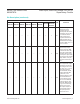

magnitude indicated (reset threshold overdrive). The
graph shows the maximum pulse width that a negative-
going V
CC
transient may typically have without causing a
reset pulse to be issued. As the amplitude of the transient
increases (i.e., goes farther below the reset threshold),
the maximum allowable pulse width decreases. A 0.1μF
bypass capacitor mounted close to the V
CC
pin provides
additional transient immunity.
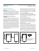
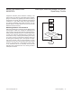
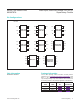
Watchdog Software Considerations
Setting and resetting the watchdog input at different points
in the program, rather than “pulsing” the watchdog input
high-low-high or low-high-low, helps the watchdog timer to
closely monitor software execution. This technique avoids
a “stuck” loop where the watchdog timer continues to be
reset within the loop, keeping the watchdog from timing
out. Figure 6 shows an example flow diagram where the
I/O driving the watchdog input is set high at the begin-
ning of the program, set low at the beginning of every
subroutine or loop, then set high again when the program
returns to the beginning. If the program should “hang”
in any subroutine, the I/O is continually set low and the
watchdog timer is allowed to time out, causing a reset or
interrupt to be issued.
Figure 6. Watchdog Flow Diagram
START
SET WDI
HIGH
PROGRAM
CODE
SUBROUTINE OR
PROGRAM LOOP
SET WDI LOW
RETURN
SUBROUTINE
COMPLETED
HANG IN
SUBROUTINE
MAX6715A–MAX6729A/
MAX6797A
Dual/Triple, Ultra-Low-Voltage, SOT23 μP
Supervisory Circuits
www.maximintegrated.com
Maxim Integrated
│
13