
Datasheet

Applications Information
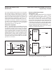
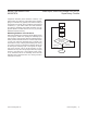
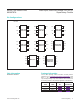
Interfacing to μPs with Bidirectional
Reset Pins
Most μPs with bidirectional reset pins can interface directly
to open-drain RST output options. Systems simultane-
ously requiring a push-pull RST output and a bidirectional
reset interface can be in logic contention. To prevent con-
tention, connect a 4.7kΩ resistor between RST and the
μP’s reset I/O port as shown in Figure 4.
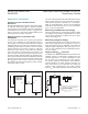
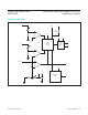
Adding Hysteresis to the Power-Fail
Comparator
The power-fail comparator has a typical input hysteresis
of 3mV. This is sufficient for most applications where a
power-supply line is being monitored through an external
voltage-divider (see the Power-Fail Comparator section).
If additional noise margin is desired, connect a resistor
between PFO and PFI as shown in Figure 5. Select the
values of R1, R2, and R3 so PFI sees V
PFI
(626mV)
when V
EXT
falls to its power-fail trip point (V
FAIL
) and
when V
IN
rises to its power-good trip point (V
GOOD
). The
hysteresis window extends between the specified V
FAIL
and V
GOOD
thresholds. R3 adds the additional hysteresis
by sinking current from the R1/R2 divider network when
PFO is logic-low and sourcing current into the network
when PFO is logic-high. R3 is typically an order of magni-
tude greater than R1 or R2.
The current through R2 should be at least 2.5μA to ensure
that the 100nA (max) PFI input current does not signifi-
cantly shift the trip points. Therefore, R2 < V
PFI
/10μA <
62kΩ for most applications. R3 will provide additional
hysteresis for PFO push-pull (V
OH
= V
CC1
) or open-drain
(V
OH
= V
PULLUP
) applications.
Monitoring an Additional Power Supply
These μP supervisors can monitor either positive or nega-
tive supplies using a resistor voltage-divider to PFI. PFO
can be used to generate an interrupt to the μP or cause
reset to assert (Figure 3).
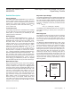
Monitoring a Negative Voltage
The power-fail comparator can be used to monitor a neg-
ative supply voltage using the circuit shown in Figure 3.
When the negative supply is valid, PFO is low. When the
negative supply voltage drops, PFO goes high. The cir-
cuit’s accuracy is affected by the PFI threshold tolerance,
V
CC
, R1, and R2.
Negative-Going V
CC
Transients
The MAX6715A–MAX6729A/MAX6797A supervisors are
relatively immune to short-duration negative-going V
CC
transients (glitches). It is usually undesirable to reset
the μP when V
CC
experiences only small glitches.
The Typical Operating Characteristics show Maximum
Transient Duration vs. Reset Threshold Overdrive, for
which reset pulses are not generated. The graph was
produced using negative-going V
CC
pulses, starting
above V
TH
and ending below the reset threshold by the
Figure 4. Interfacing to μPs with Bidirectional Reset I/O Figure 5. Adding Hysteresis to Power-Fail for Push-Pull PFO
GND GND
V
CC1
V
CC2
V
CC2
V
CC1
RST
RESET TO OTHER SYSTEM COMPONENTS
RESET
µP
4.7kΩ
MAX6715A–
MAX6729A/
MAX6797A
V
EXT
R1
R3
R2
PFI
GND
PFO
A
V
GOOD
= DESIRED V
EXT
GOOD VOLTAGE THRESHOLD
V
FAIL
= DESIRED V
EXT
FAIL VOLTAGE THRESHOLD
V
OH
= V
CC1
(FOR PUSH-PULL PFO)
R2 = 50kΩ (FOR > 10µA R2 CURRENT)
R1 = R2 ((V
GOOD
- V
PFI
) - (V
PFI
)(V
GOOD
- V
FAIL
)/V
OH
)/V
PFI
R3 = (R1 x V
OH
)/(V
GOOD
- V
FAIL
)
V
GOOD
V
FAIL
V
IN
PFO
MAX6729A
MAX6715A–MAX6729A/
MAX6797A
Dual/Triple, Ultra-Low-Voltage, SOT23 μP
Supervisory Circuits
www.maximintegrated.com
Maxim Integrated
│
12