
Datasheet
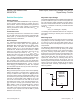

The normal watchdog timeout period (1.12s min) begins
after the first transition on WDI before the conclusion of
the long initial watchdog period (Figure 2). During the
normal operating mode, the supervisor will issue a reset
pulse for the reset timeout period if the μP does not
update the WDI with a valid transition (high-to-low or low-
to-high) within the standard timeout period (1.12s min).
Leave WDI unconnected to disable the watchdog timer.
The WDI unconnected-state detector uses a small (200nA
typ) current source. Therefore, do not connect WDI to
anything that will source more than 50nA.
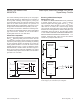
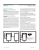
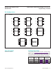
Power-Fail Comparator
PFI is the noninverting input to a comparator. If PFI is less
than V
PFI
(626.5mV), PFO goes low. Common uses for
the power-fail comparator include monitoring preregulated
input of the power supply (such as a battery) or providing
an early power-fail warning so software can conduct an
orderly system shutdown. It can also be used to monitor
supplies other than V
CC1
or V
CC2
by setting the power-
fail threshold with a resistor-divider, as shown in Figure 3.
PFI is the input to the power-fail comparator. The typical
comparator delay is 2μs from PFI to PFO. Connect PFI to
ground of V
CC1
if unused.
Ensuring a Valid Reset Output
Down to V
CC
= 0V
The MAX6715A–MAX6729A/MAX6797A are guaranteed
to operate properly down to V
CC
= 0.8V. In applica-
tions that require valid reset levels down to V
CC
= 0V,
use a pulldown resistor at RST to ground. The resistor
value used is not critical, but it must be large enough
not to load the reset output when V
CC
is above the reset
threshold. For most applications, 100kΩ is adequate. This
configuration does not work for the open-drain outputs
of the MAX6715A/MAX6717A/MAX6719A/MAX6721A/
MAX6723A/MAX6725A/MAX6727A/MAX6728A. For
pushpull, active-high RST output connect the external
resistor as a pullup from RST to V
CC1
.
Figure 2. Normal Watchdog Startup Sequence
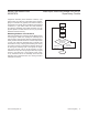
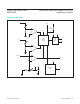
Figure 3. Using Power-Fail Input to Monitor an Additional
Power-Supply a) V
IN
is Positive b) V
IN
is Negative
1.12s MAX
t
WDI-NORMAL
1.12s MAX
t
WDI-STARTUP
35s MAX
V
TH
V
CC
WDI
RST
t
RP
R1
R2
PFI
GND
V
IN
PFO
V
TRIP
= V
PFI
R1 + R2
R2
( )
R1
R2
PFI
GND
V
CC
V
IN
PFO
V
TRIP
= R2
(V
PFI
)
1
R1
1
R2
+ -
V
CC
R1
[ ]
( )
V
PFI
= 626.5mV
A)
B)
MAX6728A/
MAX6729A/
MAX6797A
MAX6728A/
MAX6729A/
MAX6797A
MAX6715A–MAX6729A/
MAX6797A
Dual/Triple, Ultra-Low-Voltage, SOT23 μP
Supervisory Circuits
www.maximintegrated.com
Maxim Integrated
│
11