
Datasheet


HEX
96
36
3E
90
Fan-Speed Regulators and Monitors
with SMBus/I
2
C-Compatible Interface
6 Maxim Integrated
MAX6650/MAX6651
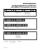
The MAX6650/MAX6651 employ three standard SMBus
protocols: write byte, read byte, and receive byte
(Figure 2). The shorter protocol (receive) allows quicker
transfers, provided that the correct data register was
previously selected by a write or read byte instruction.
Use caution with the shorter protocol in multimaster
systems, since a second master could overwrite the
command byte without informing the first master.
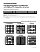
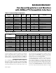
Slave Addresses
The device address can be set to one of four different
values. Accomplish this by pin-strapping ADD so that
more than one MAX6650/MAX6651 can reside on the
same bus without address conflicts (Table 1).
SMBus/I
2
C
INTERFACE
SMBus/I
2
C
INTERFACE
V
CC
3V TO 5.5V
V
CC
SCL
SDA
ADD
GND
FAN SPEED
CONFIGURE
ALARM ENABLE
ALARM STATUS
TACH COUNT
COUNT TIME
GPIO DEF
GPIO STATUS
DAC
ADDRESS
DECODE
TACHOMETER
COUNT
CONTROL
LOGIC
8-BIT
DAC
10kΩ
V
REF
GPIO
BLOCKS
(FIGURE 5)
GPIO0
OUT
FB
TACH0
GPIO1
10kΩ
90kΩ
90kΩ
10kΩ
MAX6650
MAX6651
ALERT
FULL ON
FAN
V
FAN
= 5V OR 12V
V
OFFSET
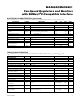
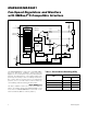
Figure 1. Block Diagram
Table 1. Slave Address Decoding (ADD)
BINARY
V
CC
1001 011
No connection (high-Z) 0011 011
10kΩ resistor to GND 0011 111
ADDRESS
ADD
1001 000GND