
Datasheet


Fan-Speed Regulators and Monitors
with SMBus/I
2
C-Compatible Interface
Maxim Integrated 15
MAX6650/MAX6651
very rough rule of thumb, 12V fans can be expected to
experience problems somewhere around 1/4 to 1/2
their rated speed.
Predicting Future Fan Failure
In systems that require maximum reliability, such as
servers and network equipment, it can be advantageous
to predict fan failure before it actually happens, to alert
the system operator before the fan fails, minimizing down
time. The MAX6650 allows the user to monitor the fan’s
condition through the following modes.
Full-On Mode
By occasionally (over a period of days or weeks) turning
the fan on full and measuring the resultant speed, a
failing fan can be detected by a trend of decreasing
speeds at a given power-supply voltage. Power-up is a
convenient time to measure the maximum fan speed.
Open-Loop Mode
The fan’s condition can also be monitored using open-
loop mode. By characterizing the fan while it is new,
fan failure can be determined by writing a predeter-
mined value to the DAC and measuring the resultant
fan speed. A decrease over time of the resultant speed
may be an indication of future fan failure.
Closed-Loop Mode
The MAX6650 allows the system to read the DAC value
used to regulate the fan speed. For a given speed, a
significant change in the required DAC value may indi-
cate future fan problems.
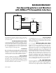
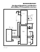
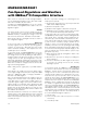
Monitoring More than 4 Fans
Use the MAX6651 to monitor up to four fans at a time
(Figure 7). For systems requiring more than four fans,
Figure 8 shows an application using an analog multi-
plexer (mux) to monitor 11 fans. GPIO2, GPIO3, and
GPIO4 are connected to the mux’s address pins. By
writing the appropriate value to the GPIO pins, the
desired tachometer gets selected and counted by the
TACH3 input. Because the TACH inputs are double-
buffered, and only sampled every other time slot, it is
important to wait at least 4 times the tachometer count
time before reading the register after changing the mux
address. In the extreme case, a total of 25 fans can be
monitored using three multiplexers connected to
TACH1, TACH2, and TACH3. Do not connect TACH0 to
a mux if the MAX6651 is under closed-loop mode.
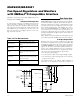
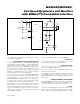
N + 1 Fan Application
As shown in Figure 9, if any MAX6650 cannot maintain
speed regulation, all other fans will automatically be
turned on full. This can be useful in high-reliability sys-
tems where any single fan failure should not cause
MAX6651
TACH0
TACH1
TACH2
TACH3
GPIO4
GPIO3
GPIO2
MAX4051
VCC
3V OR 5.5V
COM
ADDA
ADDB
ADDC
INH
GND V-
NO0
NO1
NO2
NO3
NO4
NO5
NO6
FAN TACH 4
FAN TACH 9
FAN TACH 5
FAN TACH 6
FAN TACH 7
FAN TACH 8
FAN TACH 1
FAN TACH 2
FAN TACH 3
FAN TACH 10
NO7 FAN TACH 11
TO FAN VOLTAGE
5V OR 12V
Figure 8. Monitoring Multiple Fans