
Datasheet


Fan-Speed Regulators and Monitors
with SMBus/I
2
C-Compatible Interface
12 Maxim Integrated
MAX6650/MAX6651
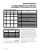
Table 8. Alarm Status Register Bit Assignments
7 (MSB) to 5
GPIO1
—
BIT
GPIO2 (MAX6651 only)
0
4
NAME
1 MIN
3
0
0 (LSB)
0
0
POR
(DEFAULT)
STATE
MAX 0
Always 0
Minimum Output Level Alarm
GPIO1 Alarm. Set when GPIO1 is low.
GPIO2 Alarm. Set when GPIO2 is low (MAX6651 only).
FUNCTION
Maximum Output Level Alarm
Tachometer Overflow Alarm2 TACH 0
The first 6 bits of the Tachometer Count-Time Register
are always zero, and the last 2 bits set the count time
(Table 9). The count time may be determined from the
following equation:
t
COUNT
= 0.25s x 2
K
COUNT
where K
COUNT
is the numerical value of the two 2LSBs.
The 0.25 factor has a ±10% uncertainty.
Upon power-up, the Tachometer Count Registers reset
to 00h and the Tachometer Count-Time Register sets a
1s integration time.
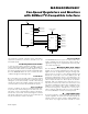
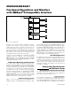
Digital-to-Analog Converter
When using the open-loop mode of operation, the DAC
Register sets the voltage on the low side of the fan. An
internal operational amplifier compares the feedback
voltage (V
FB
) with the reference voltage set by the 8-bit
DAC, and adjusts the output voltage (V
OUT
) until the
two input voltages are equal. The voltage at the FB pin
may be determined by the following equation:
V
FB
= (10 x V
REF
x K
DAC
) / 256
and the voltage across the fan is:
where K
DAC
is the numerical value of the DAC Register
and V
REF
= 1.5V. The minimum feedback voltage is
limited by the voltage drop across the external MOS-
FET (R
ON
x I
FAN
), and the maximum voltage is limited
by the fan’s supply voltage (V
FAN
). For linear opera-
V
k
k
K
V
FAN
DAC
REF
–
90
10
1
256
+
⎛
⎝
⎜
⎞
⎠
⎟
⎛
⎝
⎜
⎞
⎠
⎟
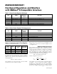
Table 9. Tachometer Count-Time Register
(Assumes two pulses per revolution)
1 = Alarm condition
REGISTER
VALUE
(K
COUNT
)
COUNT
TIME
(s)
MAXIMUM
FAN SPEED
(RPS)
MINIMUM
RESOLUTION
(Hz/COUNT)
0000 0000 0.25 512 2
12560.50000 0001
0000 0010 1.0 128 0.5
0.25642.00000 0011
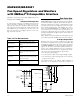
Table 7. Alarm-Enable Register Bit Masks
7 (MSB) to 5
GPIO1
—
BIT
GPIO2 (MAX6651 only)
0
4
NAME
1 MIN
3
0
0 (LSB)
0
0
POR
(DEFAULT)
STATE
MAX 0
2 TACH 0
Always 0
Minimum Output Level Alarm Enable/Disable
GPIO1 Alarm Enable/Disable
GPIO2 Alarm Enable/Disable (MAX6651 only)
FUNCTION
Maximum Output Level Alarm Enable/Disable
Tachometer Overflow Alarm Enable/Disable
1 = Enabled