
Datasheet


Alarm Status Register if the condition that caused the
alarm is removed.
Tachometer
The Tachometer Count Registers record the number of
pulses on the corresponding tachometer input during the
period defined by the Tachometer Count-Time Register.
The MAX6651 contains three additional tachometer
inputs, which may be used to monitor additional fans. For
accurate control of multiple fans, use identical fans.
The Tachometer Count-Time Register sets the integration
time over which the MAX6650/MAX6651 count tachome-
ter pulses. The devices can count up to 255 (FFh) pulses
during the selected count time. If more than 255 pulses
occur, the IC sets the overflow alarm and the Tachometer
Count Register reports the maximum value of 255. Set
the time register so the count register will not overflow
under worst-case conditions (maximum fan speed) while
maximizing resolution. Calculate the maximum measur-
able fan speed and minimum resolution with the following
equations:
Max Fan Speed (in RPS) = 255 / (2 x t
COUNT
)
Min Resolution (in RPS) = 1 / (2 x t
COUNT
)
where t
COUNT
is the tachometer count time; 1kHz is the
maximum allowable tachometer input frequency for the
MAX6650/MAX6651.
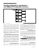
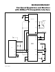
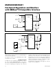
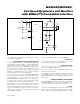
Fan-Speed Regulators and Monitors
with SMBus/I
2
C-Compatible Interface
Maxim Integrated 11
MAX6650/MAX6651
Table 5. GPIO Definition Register
Table 6. GPIO Status Register
BIT
POR
(DEFAULT)
STATE
MAX6650
PIN
MAX6651
PIN
STATE FUNCTION
0 GPIO4 outputs a logic-low level.
7 1
N/A
(must be 1)
GPIO4
1 GPIO4 outputs a logic-high level or serves as an input.
0 GPIO3 outputs a logic-low level.
6 1
N/A
(must be 1)
GPIO3
1 GPIO3 outputs a logic-high level or serves as an input.
00 GPIO2 serves as an external clock input.
01 GPIO2 serves as an internal clock output.
10 GPIO2 outputs a logic-low level.
5:4 11
N/A
(must be 11)
GPIO2
11 GPIO2 outputs a logic-high level or serves as an input.
00 GPIO1 outputs a logic-high level or serves as an input.
01 GPIO1 serves as a FULL ON input.
10 GPIO1 outputs a logic-low level.
3:2 11 GPIO1 GPIO1
11 GPIO1 outputs a logic-high level or serves as an input.
00 GPIO0 outputs a logic-high level or serves as an input.
01 GPIO0 serves as an ALERT output.
10 GPIO0 outputs a logic-low level.
1:0 11 GPIO0 GPIO0
11 GPIO0 outputs a logic-high level or serves as an input.
BIT NAME
POR
(DEFAULT
STATE)
7 (MSB) to 5 Always 0 0
4 GPIO4 (MAX6651 only) 1
3 GPIO3 (MAX6651 only) 1
2 GPIO2 (MAX6651 only) 1
1GPIO11
0 (LSB) GPIO0 1