
Datasheet


Power-on default = 0h.
D0: 0 = normal operation; 1 = shutdown.
D1: 0 = comparator mode; 1 = interrupt mode.
D2 to D3: 0 = active low; 1 = active high.
D5: 0 = normal SMBus operation; 1 = full I
2
C compatibility.
D7 to D6: Reserved locations, always write zeros.
D15: MSB is the first sign bit.
D2, D1, D0: Flag bits for T
MAX
, T
HIGH
, T
LOW
.
1 LSB = 0.0625°C.
Temperature is stored in two's complement format.
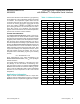
Table 4. Configuration Register
Table 3. Temperature Register
Table 2. Pointer Register Bit Assignments
D7 D6 D5 D4 D3 D2 D1 D0
0 0
SMB Timeout
Disable
Fault Queue
Enable
ALERT Po-
larity
OVERT Polar-
ity
Comparator or
Interrupt
Shutdown
D15 D14 D13 D12 D11 D10 D9 D8 D7 D6 D5 D4 D3 D2 D1 D0
MSB
(Sign)
Bit
12
Bit
11
Bit
10
Bit 9 Bit 8 Bit 7 Bit 6 Bit 5 Bit 4 Bit 3 Bit 2 Bit 1 T
MAX
T
HIGH
T
LOW
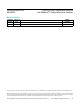
ADDRESS DESCRIPTION POR STATE
00h
Temperature register
(READ only)
0000h
01h
Conguration-Byte
register
00h
02h T
HYST
register 0100h
03h T
MAX
register 2800h
04h T
LOW
register 0500h
05h T
HIGH
register 2000h
MAX6633/MAX6634/
MAX6635
12-Bit Plus Sign Temperature Sensors
with SMBus/I
2
C-Compatible Serial Interface
www.maximintegrated.com
Maxim Integrated
│
13