
Datasheet


(V
CC
= +3.0V to +5.5V, T
A
= -55°C to +125°C, unless otherwise noted. Typical values are at V
CC
= +3.3V and T
A
= +25°C.) (Notes
2 and 3)
Note 2: Tested at a single temperature. Specifications over temperature are guaranteed by design.
Note 3: The MAX6629–MAX6632 are not specifically equipped with a shutdown function. Their low supply current permits powering
them from the output of a logic gate. This specification is given to ensure that the MAX6629–MAX6632 do not draw exces-
sive currents at low supply voltages, ensuring reliable operation from a gate output.
Note 4: Timing characteristics are guaranteed by design and are not production tested.
Note 5: C
LOAD
= total capacitance of one bus line in picofarads.
PARAMETER SYMBOL CONDITIONS MIN TYP MAX UNITS
LOGIC INPUTS (CS, SCK)
Logic Input Low Voltage V
IL
0.3 x
V
CC
V
Logic Input High Voltage V
IH
0.7 x
V
CC
V
Input Leakage Current I
LEAK
V
IN
= V
GND
or +5.5V ±1 ±5 µA
LOGIC OUTPUTS (SO)
Output Low Voltage V
OL
I
SINK
= 1.6mA 0.4 V
Output High Voltage V
OH
I
SOURCE
= 1.6mA V
CC
- 0.4 V
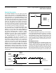
TIMING CHARACTERISTICS (Notes 4 and 5)
Serial Clock Frequency f
SCL
5 MHz
SCK Pulse Width High t
CH
100 ns
SCK Pulse Width Low t
CL
100 ns
CS Fall to SCK Rise t
CSS
C
LOAD
= 10pF 80 ns
CS Fall to Output Enable t
DV
C
LOAD
= 10pF 80 ns
CS Rise to Output Disable t
TR
C
LOAD
= 10pF 50 ns
SCK Fall to Output Data Valid t
DO
C
LOAD
= 10pF 80 ns
MAX6629–MAX6632 12-Bit + Sign Digital Temperature Sensors
with Serial Interface
www.maximintegrated.com
Maxim Integrated
│
3
Electrical Characteristics (continued)