
Datasheet


MAX6365–MAX6368
SOT23, Low-Power µP Supervisory Circuits
with Battery Backup and Chip-Enable Gating
_______________________________________________________________________________________ 7
Pin Description
PIN NAME FUNCTION
RESET
Acti ve- H i g h Reset Outp ut. RE S E T asser ts hi g h conti nuousl y w hen V
C C
i s b el ow the r eset thr eshol d ( V
TH
) ,
M R i s l ow , or RE S E T IN i s l ow . It asser ts i n p ul ses w hen the inter nal w atchd og ti m es out. RE S E T r em ai ns
asser ted for the r eset ti m eout p er i od ( t
RP
) after V
C C
r i ses ab ove the r eset thr eshol d , after the m anual r eset
i np ut g oes fr om l ow to hi g h, after RE S E T IN g oes hi g h, or after the w atchd og tr i g g ers a r eset event.
RE S E T i s an op en- d r ai n acti ve- hi g h r eset outp ut.
1
RESET
Active-Low Reset Output. RESET asserts low continuously when V
C C
is below the reset threshold
(V
TH
), the manual reset input is low, or RESET IN is low. It asserts low in pulses when the internal
watchdog times out. RESET remains asserted low for the reset timeout period (t
RP
) after V
C C
rises above the reset threshold, after the manual reset input goes from low to high, after RESET
IN goes high, or after the watchdog triggers a reset event. The MAX636_L is an active-low push-
pull output, while the MAX636_P is an active-low open-drain output.
2 CE IN
Chip-Enable Input. The input to chip-enable gating circuitry. Connect to GND or OUT if not used.
3 GND Ground
MR
MAX6365 Manual-Reset Input. Maintaining logic low on MR asserts a reset. Reset output
remains asserted as long as MR is low and for the reset timeout period (t
RP
) after MR transitions
from low to high. Leave unconnected, or connect to V
CC
if not used. MR has an internal 20kΩ
pullup to V
CC
.
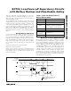
WDI
MAX6366 Watchdog Input. If WDI remains high or low for longer than the watchdog timeout
period (t
W D
), the internal watchdog timer runs out and a reset pulse is triggered for the reset
timeout period (t
RP
). The internal watchdog clears whenever reset asserts or whenever WDI sees
a rising or falling edge (Figure 2).
BATT ON MAX6367 Battery-On Output. BATT ON goes high when in battery-backup mode.
4
RESET IN
MAX6368 Reset Input. When RESET IN falls below 1.235V, reset asserts. Reset output remains
asserted as long as RESET IN is low and for at least t
RP
after RESET IN goes high.
5V
CC
Supply Voltage, 1.2V to 5.5V. Reset asserts when V
C C
drops below the reset threshold voltage
(V
TH
). Reset remains asserted until V
C C
rises above V
TH
and for at least t
RP
after V
C C
rises
above V
TH
.
6 OUT
Output. OUT sources from V
C C
when not in reset and from the greater of V
CC
or BATT when V
C C
is below the reset threshold.
7 BATT
Backup-Battery Input. When V
C C
falls below the reset threshold, OUT switches to BATT
if V
BATT
is 20mV greater than V
C C
. When V
C C
rises 20mV above V
BATT
, OUT switches to V
C C
. The 40mV
hysteresis prevents repeated switching if V
CC
falls slowly.
8 CE OUT
Chip-Enable Output. CE OUT goes low only when CE IN is low and reset is not asserted. If CE
IN is low when reset is asserted, CE OUT will stay low for 12µs (typ) or until CE IN goes high,
whichever occurs first.