
Datasheet


MAX6365–MAX6368
SOT23, Low-Power µP Supervisory Circuits
with Battery Backup and Chip-Enable Gating
______________________________________________________________________________________ 11
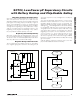
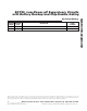
Watchdog Software Considerations
One way to help the watchdog timer monitor the soft-
ware execution more closely is to set and reset the
watchdog at different points in the program rather than
pulsing the watchdog input periodically. Figure 4
shows a flow diagram in which the I/O driving the
watchdog is set low in the beginning of the program,
set high at the beginning of every subroutine or loop,
and set low again when the program returns to the
beginning. If the program should hang in any subrou-
tine, the problem would be quickly corrected.
Replacing the Backup Battery
When V
CC
is above V
TH
, the backup power source can
be removed without danger of triggering a reset pulse.
The device does not enter battery-backup mode when
V
CC
stays above the reset threshold voltage.
Negative-Going V
CC
Transients
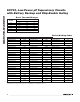
These supervisors are relatively immune to short-dura-
tion, negative-going V
CC
transients. Resetting the µP
when V
CC
experiences only small glitches is usually not
desirable.
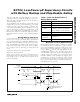
The
Typical Operating Characteristics
section has a
Maximum Transient Duration vs. Reset Threshold
Overdrive graph for which reset is not asserted. The
graph was produced using negative-going V
CC
pulses,
starting at V
CC
and ending below the reset threshold by
the magnitude indicated (reset threshold overdrive).
The graph shows the maximum pulse width that a neg-
ative-going V
CC
transient can typically have without
triggering a reset pulse. As the amplitude of the tran-
sient increases (i.e., goes further below the reset
threshold), the maximum allowable pulse width
decreases. Typically, a V
CC
transient that goes 100mV
below the reset threshold and lasts for 30µs will not trig-
ger a reset pulse.
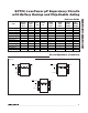
A 0.1µF bypass capacitor mounted close to the V
CC
pin provides additional transient immunity.
BATT
BATT ON
OUT
CMOS RAM
0.1µF
GND
RESET
CE IN
CE
RESET
CE OUT
MAX6367
V
CC
A0–A15
µP
+2.4V TO +5.5V
ADDRESS
DECODE
Figure 3. MAX6367 BATT ON Driving an External Pass
Transistor
Figure 4. Watchdog Flow Diagram
START
SET
WDI
LOW
RETURN
END
SUBROUTINE
OR PROGRAM LOOP
SET WDI
HIGH