
Datasheet


MAX5895
similar to the first filter and removes the images at 2f
S
, 6f
S
,
10f
S
, etc. Finally, the third filter removes images at 4f
S
,
12f
S
, 20f
S
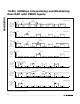
, etc. Figures 10, 11, and 12 similarly illustrate
the spectral responses when using the interpolating filters
combined with the digital modulator.
Digital Modulator
The MAX5895 features digital modulation at frequen-
cies of f
IM
/2 and f
IM
/4, where f
IM
is the data rate at the
input to the modulator. f
IM
equals f
DAC
in 1x, 2x, and 4x
interpolation modes. In 8x interpolation mode, f
IM
equals f
DAC
/2. The output rate of the modulator is
always the same as the input data rate to the modula-
tor, f
IM
.
In complex modulation mode, data from the second
interpolation filter is frequency mixed with the on-chip
in-phase and quadrature (I/Q) local oscillator (LO).
Complex modulation provides the benefit of image
sideband rejection when combined with an external
quadrature modulator commonly found in wireless
communication systems.
In the f
LO
= f
IM
/4 mode, real or complex modulation can
be used. The modulator multiplies successive input data
samples by the sequence [1, 0, -1, 0] for a cos(ωt). The
modulator modulates the input signal up to f
IM
/4, creat-
ing upper and lower images around f
IM
/4. The quadra-
ture LO sin(ωt) is realized by delaying the cos(ωt)
sequence by one clock cycle. Using complex modula-
tion, complex IF is generated. The complex IF combined
with an external quadrature modulator provides image
rejection. The sign of the LO can be changed to allow
the user to select whether the upper or the lower image
should be rejected (bit 1 of register 01h).
When f
IM
/2 is chosen as the LO frequency, the input
signal is multiplied by [-1, 1] on both channels. This pro-
duces images around f
IM
/2. The complex image-reject
modulation mode is not available for this LO frequency.
The outputs of the modulator can be expressed as:
in complex modulation, e
+jwt
in complex modulation, e
-jwt
where ω = 2 x π x f
LO
.
For real modulation, The outputs of the modulator can
be expressed as:
If more than one MAX5895 is used, their LO phases can
be synchronized by simultaneously releasing RESET.
This sets the MAX5895 to its predefined initial phase.
Device Reset
The MAX5895 can be reset by holding the RESET pin
low for 10ns. This will program the control registers to
It At t
Qt At t
cos
cos
()
=
()
×
()
()
=
()
×
()
ω
ω
It At t Bt t
Qt At t Bt t
cos sin
sin cos
()
=
()
×
()
+
()
×
()
()
=
()
×
()
+
()
×
()
ωω
ωω
It At t Bt t
Qt At t Bt t
cos sin
sin cos
()
=
()
×
() ()
×
()
()
=
()
×
()
+
()
×
()
−ωω
ωω
16-Bit, 500Msps Interpolating and Modulating
Dual DAC with CMOS Inputs
24 ______________________________________________________________________________________
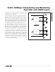
Figure 13. (a) Modulator in Complex Modulation Mode; (b) Modulator in Real Modulation Mode
sin(ωt)
sin(ωt)
cos(ωt)
cos(ωt)
I-CHANNEL
INPUT DATA
TO
FIR3
(a)
Q-CHANNEL
INPUT DATA
I-CHANNEL
OUTPUT DATA
Q-CHANNEL
OUTPUT DATA
(b)
∑
∑
sin(ωt)
sin(ωt)
cos(ωt)
cos(ωt)
I-CHANNEL
INPUT DATA
TO
FIR3
Q-CHANNEL
INPUT DATA
I-CHANNEL
OUTPUT DATA
Q-CHANNEL
OUTPUT DATA
∑
∑