
Datasheet


3) Sin(x)/x rolloff is reduced over the effective bandwidth.
Figure 9 illustrates a practical example of the benefits
when using the MAX5895 in 2x, 4x, and 8x interpolation
modes with the third filter configured as a lowpass filter.
With no interpolation filter, the first image signal appears
in the second Nyquist zone between f
S
/2 and f
S
. The first
interpolating filter removes this image. In fact, all of the
images at odd numbers of f
S
are filtered. At the output of
the first filter, the images are at 2f
S
, 4f
S
, etc. This signal is
then passed to the second interpolating filter, which is
MAX5895
16-Bit, 500Msps Interpolating and Modulating
Dual DAC with CMOS Inputs
______________________________________________________________________________________ 21
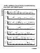
Figure 10. Spectral Representation of 4x Interpolation Filter with f
IM
/4 Modulation (Output Frequencies are Relative to the Data Input
Frequency, f
S
)
FOR COMPLEX MODULATION THE MODULATION SIGN (BIT 1, ADDRESS 01h) SELECTS UPPER OR LOWER SIDEBAND
LOWER
SIDEBAND
UPPER
SIDEBAND
f
S
2f
S
3f
S
4f
S
f
S
2f
S
3f
S
4f
S
f
S
2f
S
3f
S
4f
S
f
S
2f
S
3f
S
4f
S
f
S
2f
S
3f
S
4f
S
FILTER
RESPONSE
FILTER
RESPONSE
INPUT
SPECTRUM
AND FIRST
FILTER
RESPONSE
OUTPUT
SPECTRUM
OF THE
FIRST
FILTER
INPUT
SPECTRUM
AND
SECOND
FILTER
RESPONSE
OUTPUT
SPECTRUM
OF THE
SECOND
FILTER
OUTPUT
SPECTRUM
OF THE
MODULATOR
2x INTERPOLATION
4x INTERPOLATION
NO INTERPOLATION
SIGNAL
IMAGE
SIGNAL
IMAGE
SIGNAL
IMAGE
SIGNAL
SIGNAL
IMAGE
IMAGE