
Datasheet


MAX5895
ter is located after the modulator. In the 8x interpolation
mode, the last filter (FIR3) can be configured as low-
pass or highpass (bit 5, address 01h) to select the
lower or upper sideband from the modulation output.
The frequency responses of these three filters are plot-
ted in Figures 5–8.
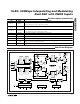
The programmable interpolation filters multiply the
MAX5895 input data rate by a factor of 2x, 4x, or 8x to
separate the reconstructed waveform spectrum and the
DAC image. The original spectral images, appearing at
around multiples of the input data rate, are attenuated
by the internal digital filters. This feature provides three
benefits:
1) Image separation reduces complexity of analog
reconstruction filters.
2) Lower input data rates eliminate board-level high-
speed data transmission.
16-Bit, 500Msps Interpolating and Modulating
Dual DAC with CMOS Inputs
20 ______________________________________________________________________________________
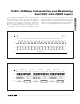
Figure 9. Spectral Representation of Interpolating Filter Responses (Output Frequencies are Relative to the Data Input Frequency, f
S
)
f
S
2f
S
3f
S
4f
S
5f
S
6f
S
7f
S
8f
S
f
S
2f
S
3f
S
4f
S
5f
S
6f
S
7f
S
8f
S
f
S
2f
S
3f
S
4f
S
5f
S
6f
S
7f
S
8f
S
f
S
2f
S
3f
S
4f
S
5f
S
6f
S
7f
S
8f
S
f
S
2f
S
3f
S
4f
S
5f
S
6f
S
7f
S
8f
S
f
S
2f
S
3f
S
4f
S
5f
S
6f
S
7f
S
8f
S
FILTER
RESPONSE
FILTER
RESPONSE
FILTER
RESPONSE
INPUT
SPECTRUM
AND FIRST
FILTER
RESPONSE
OUTPUT
SPECTRUM
OF THE
FIRST
FILTER
INPUT
SPECTRUM
AND
SECOND
FILTER
RESPONSE
OUTPUT
SPECTRUM
OF THE
SECOND
FILTER
INPUT
SPECTRUM
AND THIRD
FILTER
RESPONSE
OUTPUT
SPECTRUM
OF THE
THIRD
FILTER
2x INTERPOLATION
4x INTERPOLATION
8x INTERPOLATION
NO INTERPOLATION
SIGNAL
IMAGE
SIGNAL
IMAGE
SIGNAL
IMAGE
SIGNAL
SIGNAL
SIGNAL
IMAGE
IMAGE
IMAGE